Chain block operating angle adjusting device and slider assembling structure

An operating angle, chain hoist technology, applied in the direction of the hoisting device, the spring mechanism, etc., can solve the problems of low manufacturing qualification rate, difficult to replace, only damage when dismantling, etc., to improve the manufacturing qualification rate, easy to disassemble and assemble The effect of replacing and avoiding damage to the machine

Inactive Publication Date: 2017-02-22
CHONGQING VITAL ELEVATORING EQUIP
View PDF7 Cites 0 Cited by
  • Summary
  • Abstract
  • Description
  • Claims
  • Application Information

AI Technical Summary

Problems solved by technology

[0004] At present, when the existing hand chain hoists are in use, the assembly structure of the guide sliders is difficult to assemble the sliders, the manufacturing pass rate is low, it is not easy to replace, and the disassembly can only be damaged, the scrap rate is high, and the mass production and assembly are not easy, because the sliders are Nylon or plastic material, the original design is seriously worn out during knocking and loading, and the guide groove is not strong enough, easy to break, the guide slider is easy to get stuck with the bracelet case during assembly, and it is not easy to repair, because there is an air getter under the bayonet, which increases Difficulty in manufacturing, the size cannot be guaranteed, and the overall pass rate of the manufacturing process is not high
[0005] Moreover, when the existing chain hoists are used, most of them are used at fixed angles, which cannot adapt to some special operating environments and affect the work efficiency. Therefore, we propose a chain hoist operation angle adjustable device and Slider assembly structure

Method used


Image

  • Chain block operating angle adjusting device and slider assembling structure

Examples


Embodiment Construction

[0023] In order to make the technical means, creative features, goals and effects achieved by the present invention easy to understand, the present invention will be further described below in conjunction with specific embodiments.

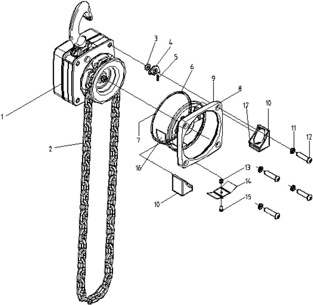
[0024] Such as figure 1 As shown, a chain hoist operating angle adjustable device and a slider assembly structure, including a hoist body 1, a slider 10 and a hand chain 2, the hoist body 1 is connected to the hand chain 2, and the outside of the hand chain 2 is A hand chain wheel cover 6 is provided, and the hand chain wheel cover 6 is sleeved on the pressure plate 8, and the pressure plate 8 is connected with the hoist body 1 through screws 12; the hand chain wheel cover 6 is provided with an enlarged opening 16, and the slider 10 is provided with There is a slider guide groove 17, and the slider 10 is connected with the hand chain wheel case 6 through the slider guide groove 17 and the enlarged opening 16. The inner side of the hand chain wheel...


PUM


Abstract

The invention discloses a chain block operating angle adjusting device and slider assembling structure. The chain block operating angle adjusting device and slider assembling structure comprises a block body, a slider and a hand pulling chain; the block body is connected with the hand pulling chain; a hand chain wheel housing is arranged at the outer side of the hand pulling chain; the hand chain wheel housing sleeves a pressing plate; the pressing plate is connected with the block body through a screw; the hand chain wheel housing is provided with an enlarged opening; the slider is provided with a slider guide groove; the slider is connected with the hand chain wheel housing via the slider guide groove and the enlarged opening; a baffle is arranged at the inner side of the hand chain wheel housing; the baffle is integrally connected with the hand chain wheel housing through the screw and a nut. The chain block operating angle adjusting device and slider assembling structure is convenient to use, accurate and reasonable in design, easy to dismount and replace, convenient to repair, free of assembly loss, simple in slider manufacturing, capable of realizing large-scale production, relatively high in percent of pass of manufacturing, capable of realizing adjustable operation of operating angle on the circumference, and suitable for wide popularization and application.

Description

[0001] 【Technical field】 [0002] The invention relates to a chain hoist, in particular to a chain hoist operating angle adjustable device and a sliding block assembly structure. [0003] 【Background technique】 [0004] At present, when the existing hand chain hoists are in use, the assembly structure of the guide sliders is difficult to assemble the sliders, the manufacturing pass rate is low, it is not easy to replace, and the disassembly can only be damaged, the scrap rate is high, and the mass production and assembly are not easy, because the sliders are Nylon or plastic material, the original design is seriously worn out during knocking and loading, and the guide groove is not strong enough, easy to break, the guide slider is easy to get stuck with the bracelet case during assembly, and it is not easy to repair, because there is an air getter under the bayonet, which increases It is difficult to manufacture, the size cannot be guaranteed, and the overall pass rate of the m...

Claims


Application Information

Patent Timeline
Patent Type & Authority Applications(China)
IPC IPC(8): B66D1/04B66D1/28
CPCB66D1/04B66D1/28
Inventor 过奇荣符想念
Owner CHONGQING VITAL ELEVATORING EQUIP
Why Eureka
Try Eureka