Method for man hand, upper limb and lower limb passive exercising

A passive movement, upper limb technology, applied in the field of mechanical technology and medical science, can solve the problem of expensive equipment

Inactive Publication Date: 2007-10-24
朱铁成
View PDF0 Cites 13 Cited by
  • Summary
  • Abstract
  • Description
  • Claims
  • Application Information

AI Technical Summary

Problems solved by technology

[0002] In the existing technology, most of the passive movements of hands, upper limbs and lower limbs are performed by physical therapists or escorts. If it is done by equipment, such equipment is also very expensive

Method used


Image

  • Method for man hand, upper limb and lower limb passive exercising
  • Method for man hand, upper limb and lower limb passive exercising
  • Method for man hand, upper limb and lower limb passive exercising

Examples


Embodiment 1

[0016] Further explanation is carried out below in conjunction with specific embodiment one:

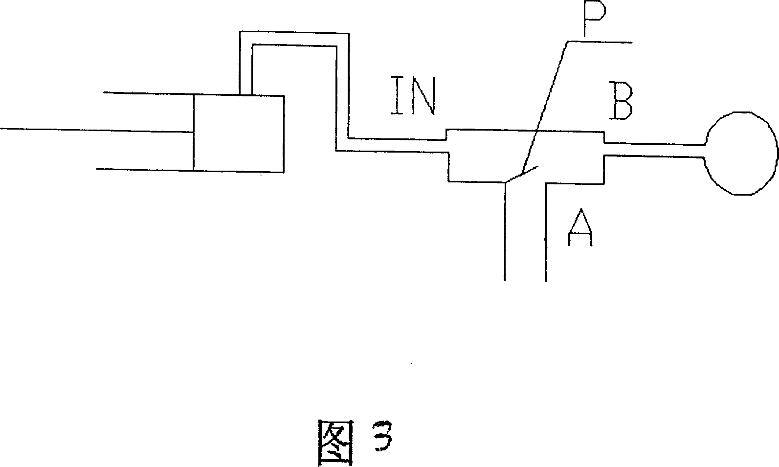
[0017] Air bag (balloon) is positioned under the palm in this example and is realized by strap, and air bag (balloon) and strap are fixed together, and strap can bind the user's bowl.

[0018] The working process of the manual passive movement embodiment is: after the air pump works, inflate the three-way valve from the IN port, the valve plate P covers the A port, and the air directly enters the air bag (balloon), and the air bag (balloon) is inflated. To a certain extent, the valve plate P rotates to cover the IN port, and the air in the air bag (balloon) is released from the B port of the three-way valve to the A port, and the air bag (balloon) is deflated. Certainly also can select the pump that can pump air also can carry out above-mentioned work for use, does not need three-way valve like this, and the mode of realization is thousands of kinds, does not add discussion here.

Embodiment 2

[0020] The example in Figure 5 is that a person takes a sitting posture, and a point suitable for traction is constructed at a suitable position on the upper part of the chair where the person sits. A power source is arranged on this point, and the action of this power source can drive the movement of the upper and lower limbs.

[0021] Below by the specific embodiment two that adapts to it, this invention is described further:

[0022] In Fig. 5, the person gets sitting posture and sits on a chair, and one end of the traction rope 1 is connected to the foot bowl and the sole of the foot of the lower limb. The other end is wound on the motor 7 through the guide wheels 2, 4, 5, the guide wheels 2, 4, 5 are fixed on the bracket 3, the motor 7 rotates forward, the traction rope is wound more towards the motor 7, and the lower limbs are pulled by the traction rope 1 to move upwards ;vice versa.

[0023] The traction of the lower limbs can be realized by hanging the soles of the f...

specific Embodiment 3

[0028] The difference from example 2 is that by adding guide wheel 15 and hand mechanism 16, the motor can be replaced by the user to control the amount of movement. The traction rope 1 passes through guide wheels 2, 4, 5 and is wound on the hand mechanism 16 through guide wheel 15. On the spool, the hand crank mechanism 16 can also use a worm gear mechanism to save labor; the winding mechanism can also be wound in the manner shown in Figure 9, the basic idea is that a large circle has a small circle, and the large circle 18 is manually moved, and the rope is wound on the shaft. (Small circle) On 17, the shaft diameter of 17 is very small, such as 30 millimeters, and the large circle that is moved by hand can have a larger diameter, such as 300 millimeters, which saves 10 times the power when pulling.


PUM


Abstract

The invention provides a method for the passive motion of human hand, upper limb and lower limb. The hand passive motion is to put air bag below palm and make hand on it open and contract passively by aerating and degassing the air bad. The extension of upper limb and lower limb is to select proper extension points on upper and lower limbs, and realizes passive exercises around shoulder joint or hip joint through extension rope's motion. The invention can increase exercise amount for hand, upper limb and lower limb, especially suitable for patients with cerebral thrombus. It can help them to recovery and prevent further limb atrophy.

Description

technical field [0001] The invention relates to mechanical technology and medical science, and in particular provides a method for passive movement of human hands, upper limbs and lower limbs, which can be used as a fitness device, and can also be used as a medical rehabilitation device after clinical practice. Background technique [0002] In the prior art, most of the passive movements of hands, upper limbs, and lower limbs are performed by physical therapists or escorts. If it is done by equipment, such equipment is also very expensive. Contents of the invention [0003] A method for passive movement of human hands, upper limbs and lower limbs of the present invention can provide passive movement of hands, upper limbs and lower limbs, through this passive movement, the amount of exercise of hands, upper limbs and lower limbs can be increased, and the passive movement of hands, upper limbs and lower limbs can be continuously improved. Stimulating the nervous system that ...

Claims


Application Information

Patent Timeline
Patent Type & Authority Applications(China)
IPC IPC(8): A61H1/00A63B23/035
Inventor 朱铁成
Owner 朱铁成
Why Eureka
Try Eureka