
Winding device

A technology of winding and control devices, which is applied in transportation and packaging, melt spinning, current collectors, etc., and can solve problems such as difficult spindle frame rotation centers

Inactive Publication Date: 2012-02-01
SAURER GMBH & CO KG
View PDF11 Cites 0 Cited by
  • Summary
  • Abstract
  • Description
  • Claims
  • Application Information

AI Technical Summary

Problems solved by technology

In this regard, depending on the number of actuators and sensors, long rotary conveyors have to be used, but this is difficult to install in the center of rotation of the spindle carrier

Method used

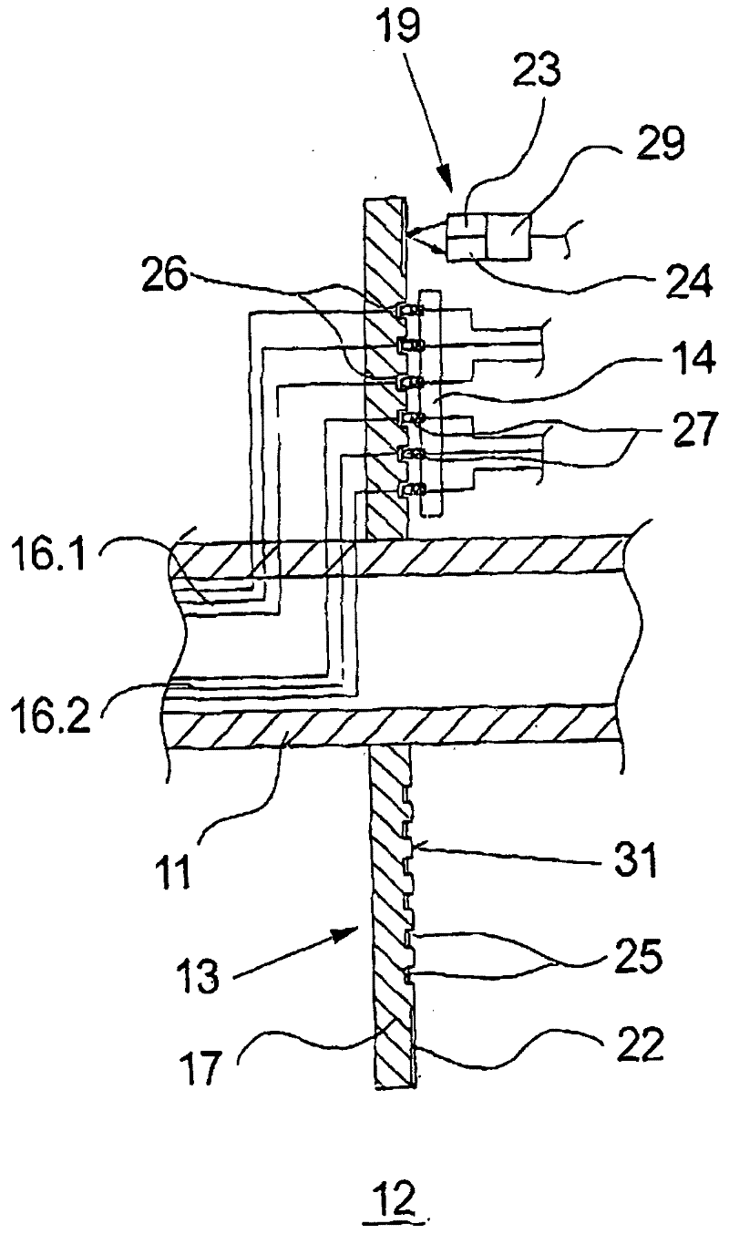
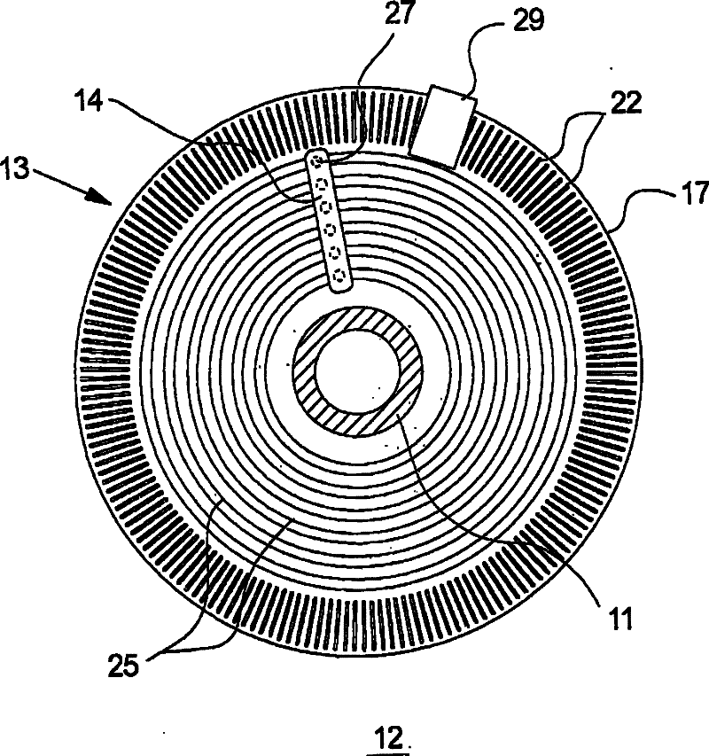

Image

  • Winding device
  • Winding device
  • Winding device

Examples


Embodiment Construction

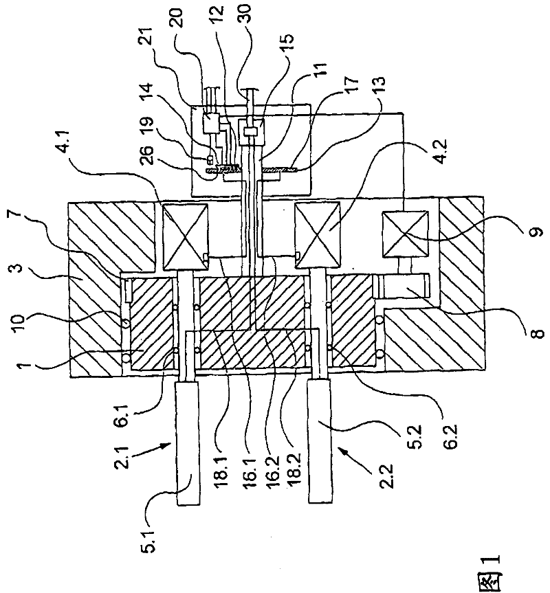
[0024] figure 1 The first embodiment of the winding device of the present invention is schematically shown in cross-sectional view.

[0025] This exemplary embodiment shows a spindle carrier 1 which is designed in the form of a cylinder and is mounted rotatably in a housing 3 via a housing bearing 10 . The spindle carrier 1 has a ring gear 7 on its circumference, which is connected via a transmission 8 to a geared motor 9 for driving the spindle carrier 1 . The geared motor 9 is controlled by a control device 20 .

[0026] Two winding spindles 2.1 and 2.2 are rotatably mounted on the spindle carrier 1 at a distance from one another, in particular offset from one another by 180°, via bearings 6.1 and 6.2. The bobbin spindles 2.1 and 2.2 are connected at one end to a spindle motor 4.1 and 4.2 respectively. The spindle motor 4.1 is arranged on the bobbin spindle 2.1, and the spindle motor 4.2 is arranged on the bobbin spindle 2.2. On the opposite side of the spindle carrier 1...


PUM


Abstract

The invention relates to a winding device for continuous winding of filaments, comprising a plurality of bobbin spindles arranged on a rotatably driven spindle rest. In this case, the actuating elements assigned to the bobbin spindles for supporting and forming the package are connected to a stationary control device via at least one rotary transmission, which has a plurality of sliding contact points between a rotor and a stator. In order to achieve a compact design that is as close as possible to the spindle carrier, the rotor according to the invention is formed by a flat contact disk. Wherein the sliding contact parts are designed side by side on one end face of the contact disc.

Description

technical field [0001] The present invention relates to a winding device for continuous winding of filaments. Background technique [0002] As is well known in the manufacture of synthetic filaments in a melt spinning process, the filaments are wound continuously into packages by winding means. For this reason, the known winding device has a rotatably driven spindle rest, which supports at least two cantilevered bobbin spindles that are rotatably supported, and they alternately enter a working position for winding filaments and a reel changer. Replacement position for empty bobbins. In such winding devices it is therefore necessary to supply energy and control the actuators assigned to the bobbin spindles for supporting and forming the packages via so-called rotary transmissions. Such a winding device is known, for example, from DE 199 15 236 A1. [0003] In the known winding device there is provided a rotary conveyor for powering the compressed air-driven actuators and a...

Claims


Application Information

Patent Timeline
Patent Type & Authority Patents(China)
IPC IPC(8): D01D5/08B65H54/40B65H67/04
CPCB65H2701/31B65H67/048H01R39/10B65H54/74
Inventor A·布伦贝格
Owner SAURER GMBH & CO KG
Learn More