
Folding type ICT needle bed fixture

A folding and needle bed technology, applied in the field of jigs, can solve the problems of structural deformation of the probe, broken and deformed plastic shell, no protection, etc., to prevent dust deposition, improve service life, and prevent shell damage.

Inactive Publication Date: 2007-10-24
HAIER GRP CORP +1
View PDF0 Cites 3 Cited by
  • Summary
  • Abstract
  • Description
  • Claims
  • Application Information

AI Technical Summary

Problems solved by technology

The existing needle bed fixture has the following defects: 1) The fixture does not contain any dustproof and protective devices, so the probe is always exposed to the air, which is easy to cause the oxidation of the probe, thereby affecting the test quality of PCBA; 2) the air There is a lot of dust in the middle, because the probe is exposed, so the dust is easy to accumulate on the probe and affect the test quality of PCBA; 3) Since the probe is exposed, there is no effective protection, so when the fixture is subjected to external impact, the probe The pins are easy to be impacted or squeezed by the outside at the same time, which will cause the structural deformation of the probe, which will affect the test quality of the PCBA in the slightest, and can no longer be used in severe cases; 4) The connector on the main body is also exposed to the air, so the connector The connecting pins of the connectors are also directly in contact with the air, which is easy to form the oxidation of the metal connecting pins, which directly affects the test quality of the PCBA, and the connector has no effective protective structure. When the main body is impacted or squeezed by the outside, the plastic shell of the connector It is experienced that it is broken and deformed due to impact or extrusion, so that the connector cannot detect the PCBA, so the overall fixture can no longer be used for PCBA detection; 5) In addition, because the probe of the existing fixture is directly extended out of the protective needle plate, and the connector is located on the side of the main body. Neither the probe nor the connector can be squeezed or impacted. Occupy a very large area during the process, or manufacture special storage cabinets to store the above-mentioned jigs, and the manufacture of these storage cabinets will not only increase the cost, but also need to occupy a certain amount of storage space when the jigs are taken out for use. Space can not be fully utilized

Method used


Image

  • Folding type ICT needle bed fixture
  • Folding type ICT needle bed fixture
  • Folding type ICT needle bed fixture

Examples


Embodiment Construction

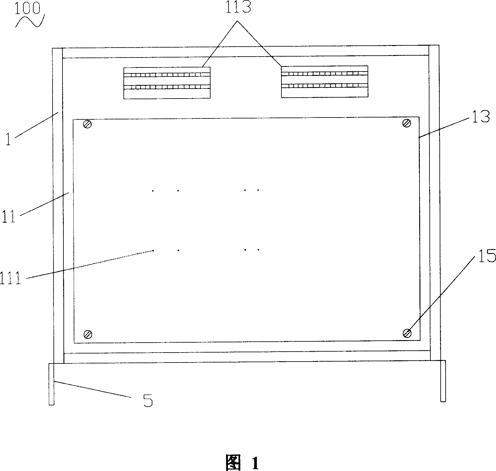
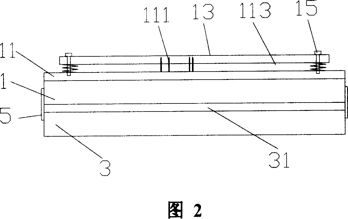
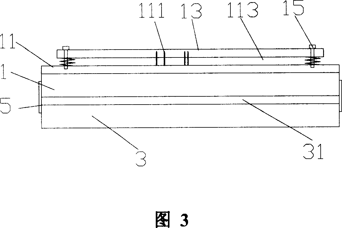
[0024] Please refer to shown in Fig. 1, the foldable ICT (IN-CIRCUIT TESTER, online testing platform) needle bed jig 100 of the present invention includes a main body frame 1, a needle board 11 arranged on the main body frame 1, and a probe arranged on the needle board 11. The needle 111 , the connector 113 , and the needle guard 13 arranged on the needle plate 11 . A cover body (not labeled) and a rotating device 5 that rotatably connects the cover frame 3 and the main body frame 1 .

[0025] Please refer to FIG. 2 and FIG. 3 at the same time, the four corners of the needle guard 13 are fixed on the needle plate 11 by the positioning member needle guard 15 , and the needle guard 13 is adjacent to the front edge of the needle guard 11 . The probes 111 are fixed on the needle plate 11 and are located below the needle guard plate 13. The number and arrangement of the probes 111 are the same as those of the existing ICT needle bed fixture, so in Fig. 1-Fig. 3 only schematically ...


PUM


Abstract

The invention discloses a foldable ICT needle bed tool, comprising a body frame, a needle plate fixed on the body frame, probes on the needle plate, and a cover, wherein when the foldable ICT needle bed is in use, the cover is under the body frame, when the cover completely covers the probes, the depth of a contain space of a cover plate frame of the cover is not smaller than the height of the highest element on the needle plate. In storage and transmission, the cover plate frame and the cover plate cover the probes, to avoid oxidizing the probes and dust, impact or compression, to confirm the test accuracy of PCBA and the service life of probes. And when stores a plurality of foldable ICT needle bed tools, the tools can be folded and stored together to save space, without special storage cabinet, to save cost.

Description

technical field [0001] The invention relates to a jig, in particular to a foldable ICT needle bed jig with a reversible cover plate. Background technique [0002] At present, the existing needle bed fixtures are generally composed of a main body. A connector is arranged on the rear side of the main body. Fixed arms are respectively provided on both sides of the bottom of the main body. The fixed arms are convenient for fixing the main body. There is a needle guard at a certain distance from the upper surface, and several probes are arranged on the main body and pass through the needle guard upwards. The arrangement order of the connectors is from bottom to top, from right to left, and the number of the connectors is from Small and big. The existing needle bed fixture has the following defects: 1) The fixture does not contain any dustproof and protective devices, so the probe is always exposed to the air, which is easy to cause the oxidation of the probe, thereby affecting t...

Claims


Application Information

Patent Timeline
IPC IPC(8): G01R1/02G01R31/00
Inventor 李勇德王震宇韩东赵希祥
Owner HAIER GRP CORP
Learn More