

Organic EL device and its manufacture method
A technology of electroluminescence and manufacturing methods, which is applied in the direction of electroluminescent light sources, electric light sources, lighting devices, etc., and can solve the problems of general products without structure and inconvenience
- Summary
- Abstract
- Description
- Claims
- Application Information
AI Technical Summary
Problems solved by technology
Method used
Image

Examples
no. 1 example
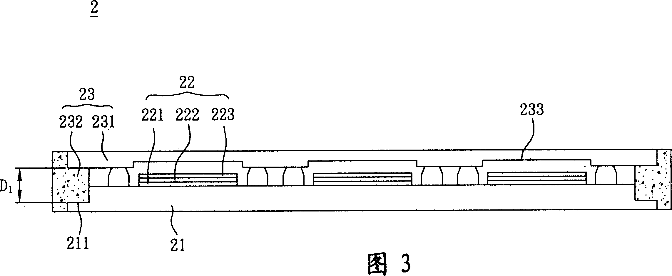
[0049] Please refer to FIG. 3 , an organic electroluminescent device 2 according to a preferred embodiment of the present invention includes a substrate 21 , at least one organic electroluminescent element 22 and a packaging unit 23 .
[0050] The substrate 21 includes at least one first recessed area 211 adjacent to an edge of the substrate 21. In this embodiment, as shown in FIG. It is adjacent to the periphery of the substrate 21 , so that the peripheral thickness of the substrate 21 is smaller than other parts of the substrate 21 . The substrate 21 is selected from at least one of rigid substrates, flexible substrates, glass substrates, plastic substrates, and silicon substrates, and the material of the substrate 21 is selected from at least one of polymethylmethacrylate, plastic, polymer, glass, and silicon. one.
[0051] Please refer to FIG. 3 , the organic electroluminescent element 22 includes a first electrode 221 , at least one organic functional layer 222 and a sec...
no. 2 example
[0058] Please refer to FIG. 7 , an organic electroluminescent device 4 according to a preferred embodiment of the present invention includes a substrate 41 , at least one organic electroluminescent element 42 and a packaging unit 43 .
[0059] Since the components, materials, arrangement relationships and functional features of the substrate 41 and the organic electroluminescence element 42 in this embodiment are the same as those described in the first embodiment, they are not repeated here.
[0060] In this embodiment, the encapsulation unit 43 covers the organic electroluminescent element 42 and includes a cover plate 431 and an adhesive 432. The cover plate 431 includes at least one first recessed area 433 adjacent to the cover plate 431. On the edge, as shown in FIG. 7 , the first recessed area 433 is adjacent to the periphery of the cover plate 431 , so that the distance D2 between the substrate 41 and the first recessed area 433 of the cover plate 431 is greater than 15 ...
no. 3 example
[0064] Please refer to FIG. 8 , a substrate 30 of an organic electroluminescent device according to a preferred embodiment of the present invention includes a body 31 and at least one recessed region 32 , and the recessed region 32 is adjacent to an edge of the body 31 .
[0065] The main body 31 of this embodiment can be applied like the substrate 21 of the first embodiment, and can also be applied like the cover plate 231 of the first embodiment, for example, at least one accommodating area 233 can be formed on the main body 31 (As shown in FIG. 3 ), the material and structural features of the body 31 of this embodiment are all as described above, so they will not be described in detail here; and the setting relationship of the recessed area 32 of this embodiment can be the first embodiment. The application of the first recessed area 211 and the second recessed area 234 (as shown in FIG. 4 ) will not be repeated here.
[0066] In addition, the substrate 30 of this embodiment...
PUM
 Abstract
Description
Claims
Application Information