Thin heat radiation machine

A heat dissipation mechanism and thin technology, which is applied in cooling/ventilation/heating transformation, instrument cooling, instrument and other directions, can solve the problems of limited total thickness, miniaturization of cooling fans, etc., and achieve the effect of reducing activation power consumption

Inactive Publication Date: 2007-10-24
SUNONWEALTH ELECTRIC MACHINE IND
View PDF1 Cites 33 Cited by
  • Summary
  • Abstract
  • Description
  • Claims
  • Application Information

AI Technical Summary

Problems solved by technology

[0008] However, although the above-mentioned conventional structure has greatly reduced the overall thickness of the cooling fan, because the circuit board of this conventional structure is fixed with the coil and the silicon steel sheet in an adhesive bonding manner, it is limited by the overall thickness after the coil and the

Method used


Image

  • Thin heat radiation machine
  • Thin heat radiation machine
  • Thin heat radiation machine

Examples


no. 1 example

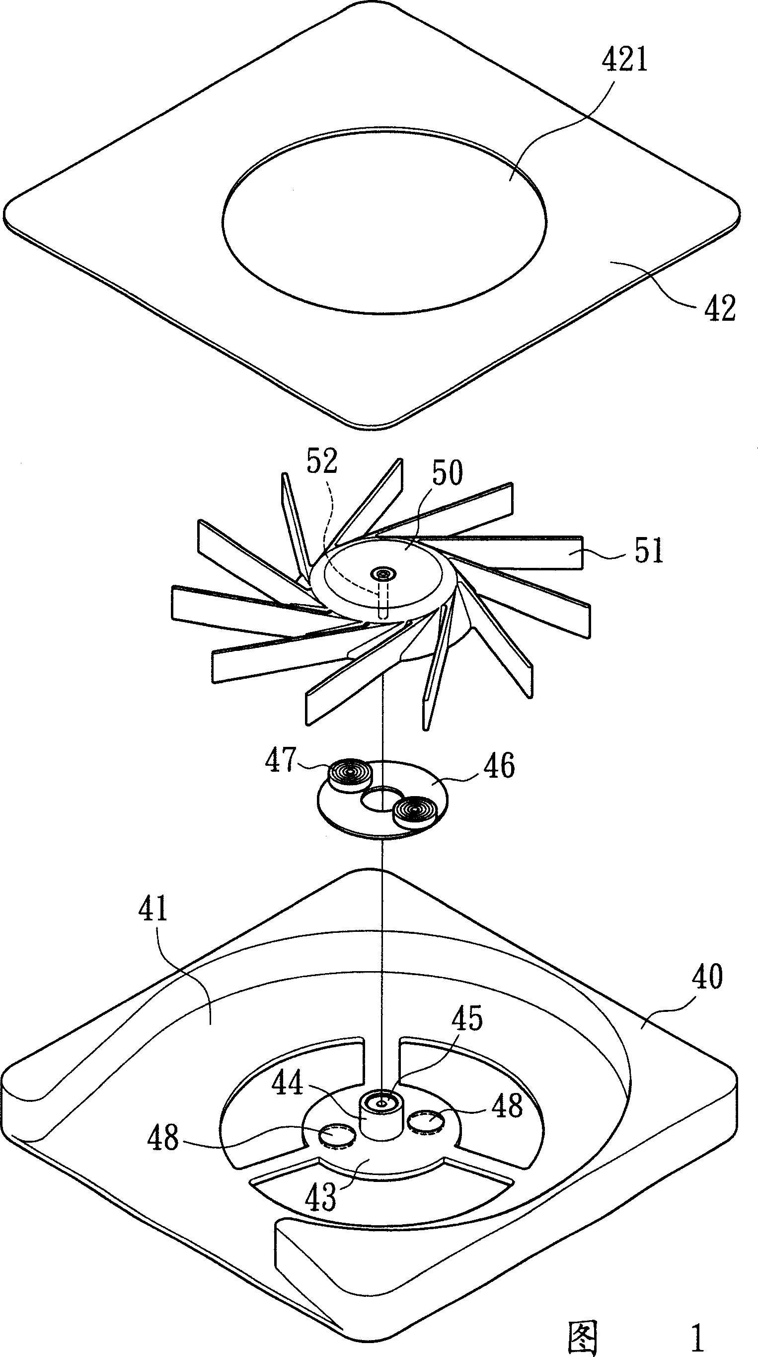
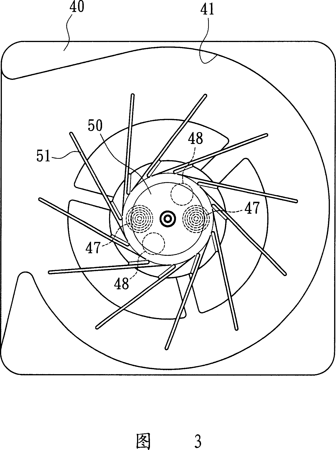
[0020] Referring to Fig. 1, the first embodiment of the present invention, the thin heat dissipation mechanism mainly includes: a frame body 40, which has an accommodating space 41 for a fan wheel rotor 50 to be arranged therein, above the frame body 40 The cover is provided with a cover plate 42, and the cover plate 42 is provided with an air inlet 421 corresponding to the fan wheel rotor 50, so when the fan wheel rotor 50 rotates, the several blades 51 extended on its periphery can drive the airflow to be sucked from the air inlet 421 , and then blow out from the air outlet on one side of the accommodating space 41 to dissipate heat from the electronic heating element;

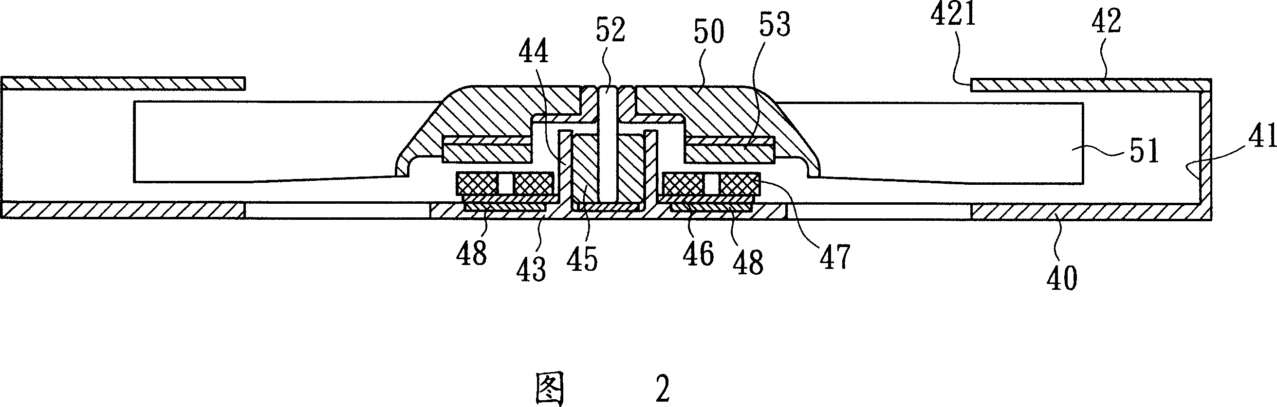
[0021] Please refer to FIG. 2, the base 43 for installing the fan wheel rotor 50 is provided at the bottom of the accommodation space 41, the circuit board 46 and the coil 47 are provided on the base 43, and a shaft tube 44 protrudes from the center of the base 43. The shaft tube 44 has a built-in bearing 45...


PUM


Abstract

The disclosed thin heat dispersion device comprises: a fan-wheel rotor arranged on base, at least two location elements with magnetic flux effect on base away the axis. This invention can avoid rotor flying out, draws the rotor to stop on optimal active angle and prevents on the active dead point to reduce the power consumption for activation.

Description

technical field [0001] The invention relates to a thin heat dissipation mechanism, in particular to a thin heat dissipation mechanism which uses magnetism to attract fan wheel rotors to locate at an optimal activation angle when stationary to reduce activation power consumption. Background technique [0002] Although the layout of integrated circuits is becoming more and more sophisticated and complex, consumers prefer light, thin, short, and small products, especially for personal 3C electronic products that pay attention to refinement. Relatively speaking, the internal heat dissipation unit Thinning is an inevitable development trend. [0003] Taiwan Application No. 84209577 Patent Announcement 265801 "Combined Structure of Small Heat Dissipating Fan Motor" is a specific design for thinning the heat dissipation unit structure, which consists of a frame 1, a stator component 2 and a rotor component 3; [0004] The inside of the frame 1 is provided with a base plate 11, the...

Claims


Application Information

Patent Timeline
IPC IPC(8): H05K7/20H01L23/467G12B15/04
Inventor 洪银树尹佐国
Owner SUNONWEALTH ELECTRIC MACHINE IND
Why Eureka
Try Eureka