Device and method for electrolytically treating work pieces

A technology for electrolytic treatment and workpiece, applied in electrolytic components, printed circuit liquid treatment, electrolytic process, etc., can solve problems such as unproven, and achieve low-cost effects

Inactive Publication Date: 2007-10-24
ATOTECH DEUT GMBH
View PDF2 Cites 8 Cited by
  • Summary
  • Abstract
  • Description
  • Claims
  • Application Information

AI Technical Summary

Problems solved by technology

Although this protective cabin is used to prevent impurities from falling into the tank, this device has not proven to solve the problems mentioned above in this article

Method used


Image

  • Device and method for electrolytically treating work pieces
  • Device and method for electrolytically treating work pieces
  • Device and method for electrolytically treating work pieces

Examples


Embodiment Construction

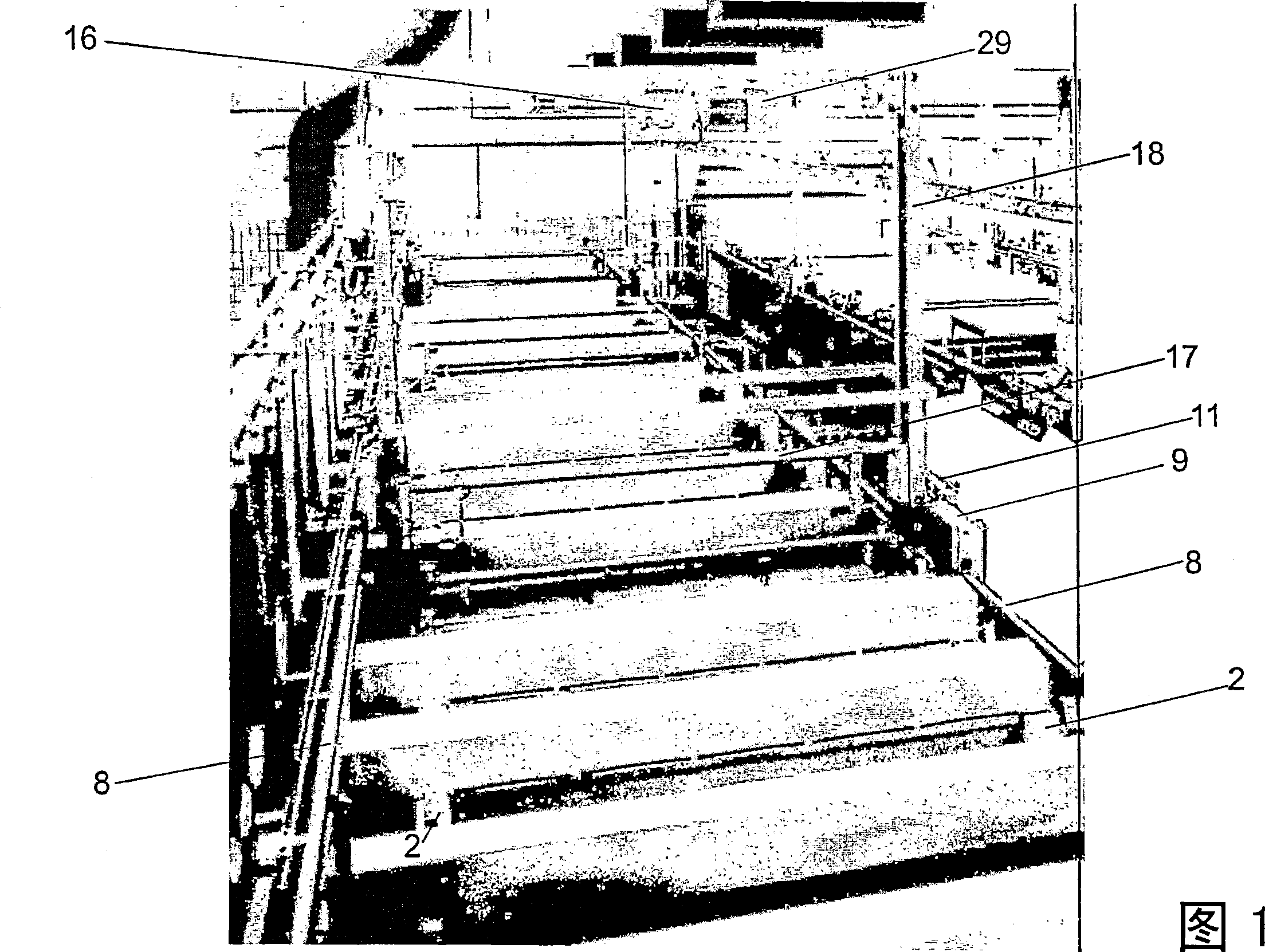
[0084] Figure 1 shows a prior art device for treating the surface of a workpiece. Devices of this type consist of a specific number of process tanks 2 arranged one behind the other to form a column of tanks. Transversely with the storage tank column, the track 8 is placed, and the transport vehicle frame 18 with the moving mechanism 9 driven by the transfer motor 11 moves on the track 8 from one processing storage tank to the next processing storage tank, and each transport vehicle frame has a A lifting mechanism 16 for moving the lifting beam 17 up and down of a transverse member. A flight bar (not shown) may be secured to a lifting beam with brackets to hold a workpiece or with clamps for directly securing a workpiece attached to the flight bar. A lift mechanism is used to lift the workpiece out of the processing tank and lower the workpiece into the processing tank, which is open towards the top end.

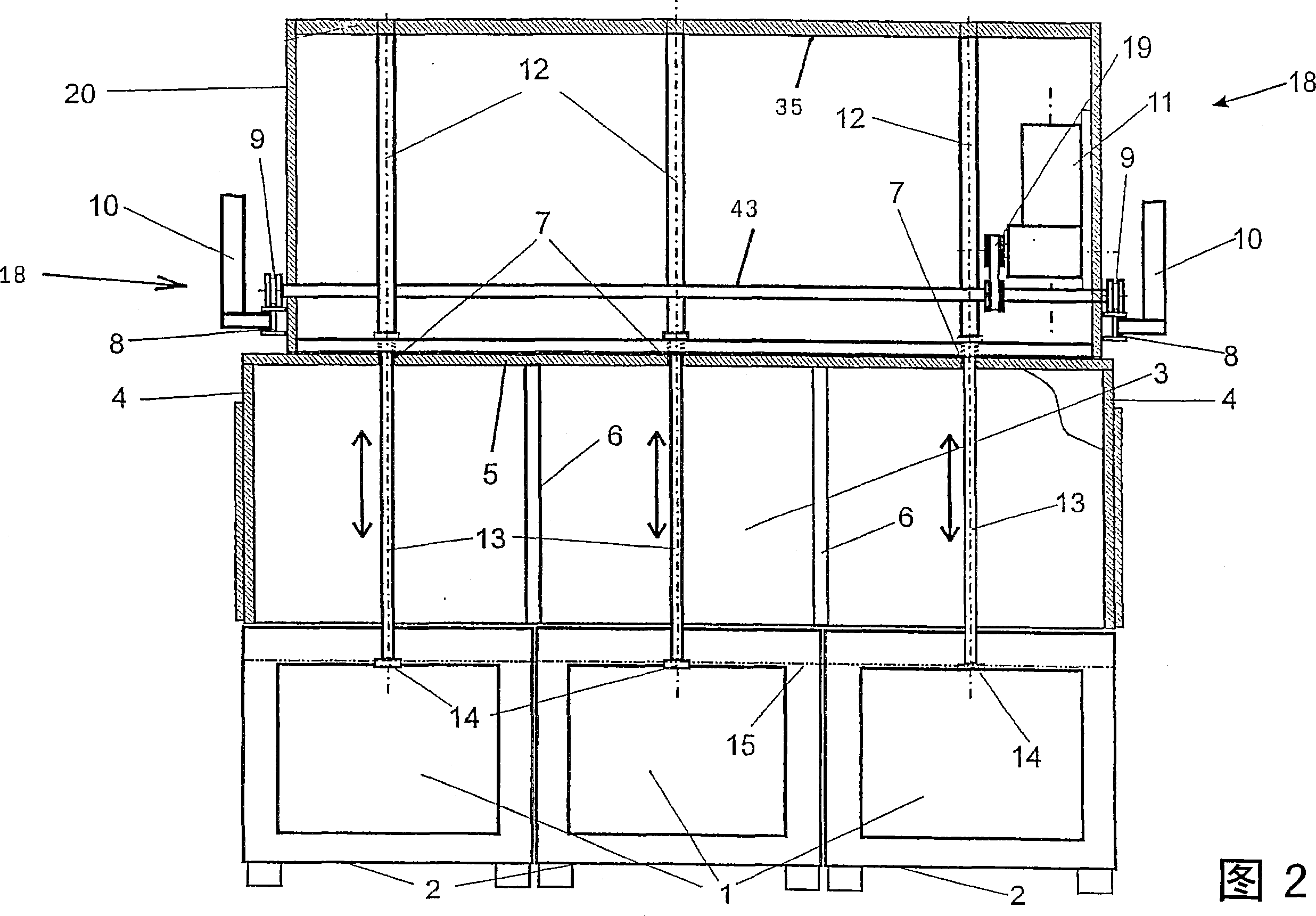
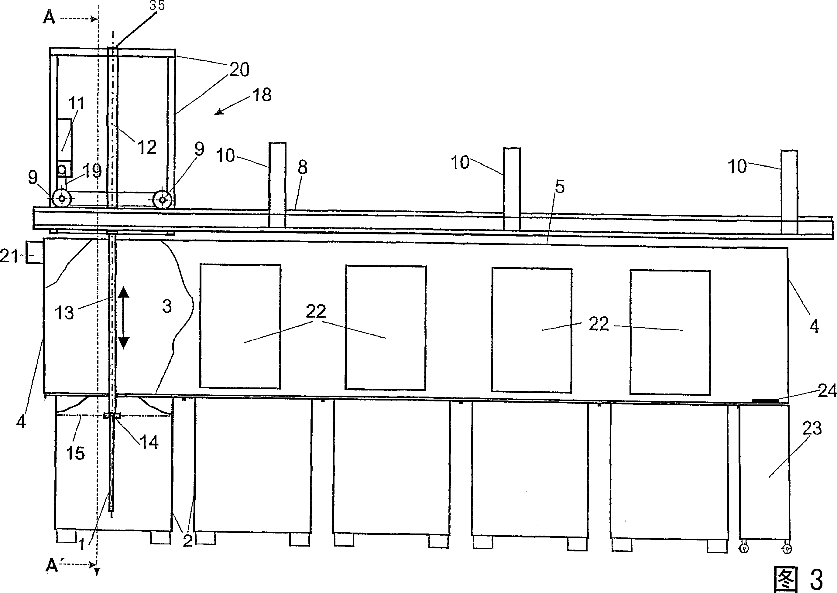
[0085] Figure 2 is a cross-sectional front view of a preferred embodim...


PUM


Abstract

The present invention provides methods for reducing the foreign body reaction against a structure implanted within an animal body. The methods include the step of providing an amount of an MMP-9 antagonist at the site of the implanted structure that is sufficient to reduce the foreign body response against the structure. The invention also provides implantable medical devices that include a surface layer that includes an amount of an MMP-9 antagonist sufficient to reduce the foreign body response against the device.

Description

technical field [0001] The invention relates to a device and a method for the chemical or electrolytic treatment of workpieces, preferably flat, highly sensitive workpieces in printed circuit technology, more particularly, for example as for the next generation of flip-chip substrates The invention also relates to the use of the device for workpieces that must have smooth surfaces or extremely fine structures as required. Background technique [0002] In the semiconductor industry, chipmakers are preparing to release what they call 90-nanometer structures. They are planning even smaller 70nm structures. But even these dimensions are only intermediate steps on the way to even smaller structures. In view of the increasing miniaturization of semiconductor components, manufacturers of printed circuit boards with chip carriers are faced with new challenges which they try to meet by adapting their products to new conditions. This means that they must meet the requirements of to...

Claims


Application Information

Patent Timeline
Patent Type & Authority Applications(China)
IPC IPC(8): C23C18/16C25D17/02C25D7/12B65G49/04
CPCC23C18/1601C23C18/1619C25D7/12C25D17/02H05K3/0085C23C18/1632C23C18/163C25D17/00C25D17/06
Inventor 赖因哈德·施奈德
Owner ATOTECH DEUT GMBH
Why Eureka
Try Eureka