Rotary damper device

A damper and shell technology, applied in the direction of shock absorbers, shock absorbers, liquid shock absorbers, etc., can solve the problems of low durability, difficult braking torque accuracy, valve damage, etc., to improve durability and accuracy. Effect

Inactive Publication Date: 2007-10-31
NIFCO INC
View PDF1 Cites 2 Cited by
  • Summary
  • Abstract
  • Description
  • Claims
  • Application Information

AI Technical Summary

Problems solved by technology

[0004] Since the valve of the above-mentioned damper device can be moved and rotatably arranged, the required braking torque cannot be obtained by means of the viscous fluid passing through the gap with the casing, and it is difficult to maintain a certain accuracy of the braking torque.
[0005] In addition, since a large load is applied to the valve, the valve may be damaged and its durability is low.

Method used


Image

  • Rotary damper device
  • Rotary damper device
  • Rotary damper device

Examples


Embodiment Construction

[0051] Hereinafter, embodiments of the present invention will be described with reference to the drawings.

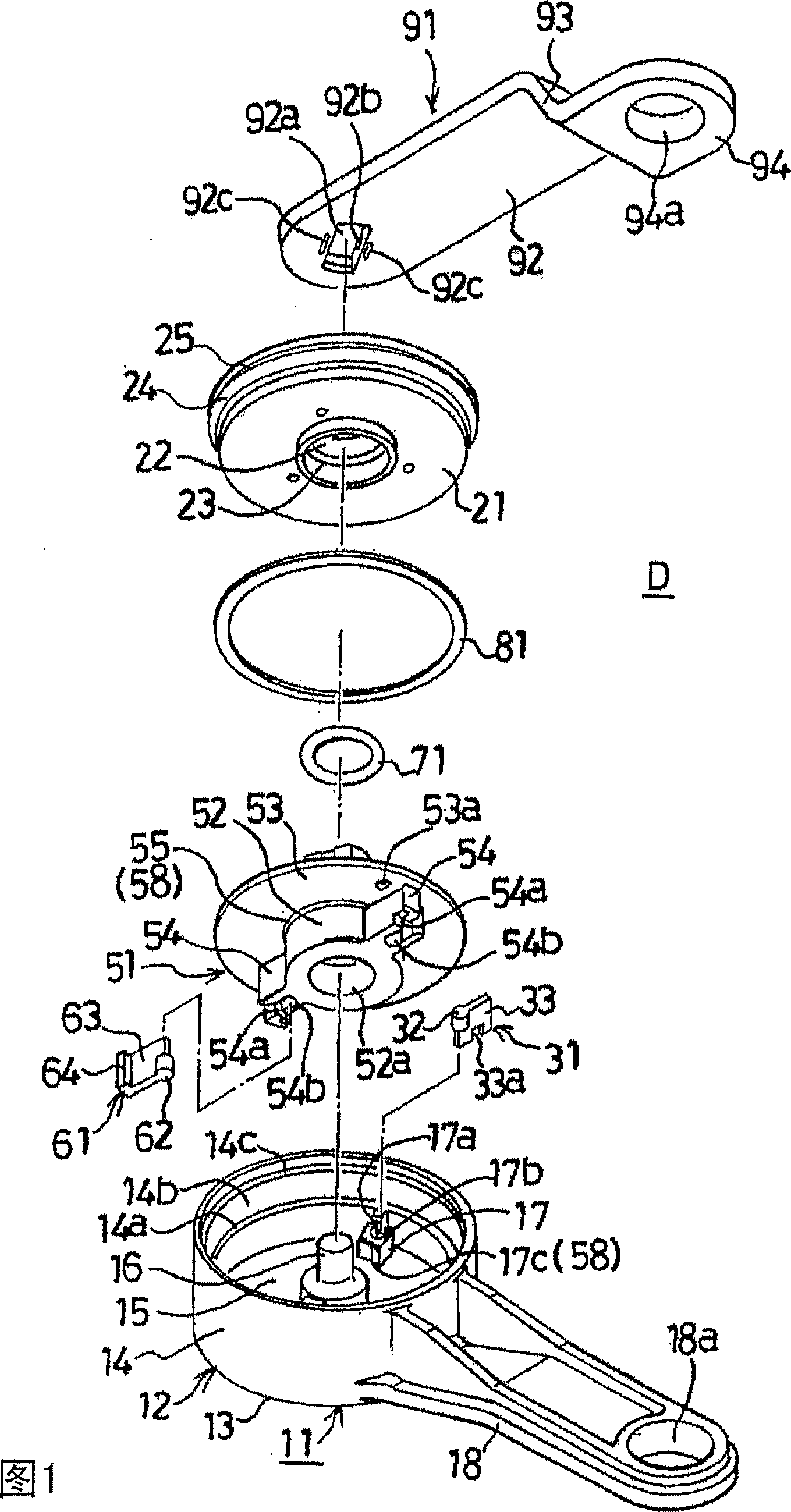
[0052] FIG. 1 is an exploded perspective view of a damper device according to an embodiment of the present invention.

[0053] In Fig. 1, D represents the damper device, and is made up of the following parts: by having rigid synthetic resin such as the housing 11 that polycarbonate is made; For example, a cover 21 made of polycarbonate; a second valve 31 made of synthetic resin, such as polyacetal, installed on the second rotor wing at the bottom of the housing 11; viscous fluid silicone oil 41 in the casing 11 (accommodation portion 15); rotatably installed in the casing 11, having a part of the shaft portion 52 protruding from the through hole 22 of the cover 21 to the outside, made of synthetic resin such as polycondensation Rotor 51 made of aldehyde; Installed on the first rotating wing 54 on this rotor 51, is made of non-swellability to viscous liquid such as sili...


PUM


Abstract

The invention provides a damper device capable of keeping constant accuracy of braking torque and improving the durability by not applying heavy load to a valve. In this damper device D composed of the housing 11, 21, the silicone oil 41 accommodated in the housing, a rotor 51 rotatably accommodated in the housing, and an O-ring 71 for preventing the leakage of the silicone oil from between the rotor and the housing, a first rotary blade 54 moved in the circumferential direction in the silicone oil 41, extended in the radial direction to define the accommodating part 15 of the housing 11, 21 accommodating the silicone oil 41, and having a notch 54a, is mounted on the rotor 51, and a first valve 61 made out of an elastically deformable elastic member is mounted on the first rotary blade 54 for opening the notch 54a in rotating the rotor 51 in one direction and closing the notch 54a in rotating the rotor 51 in the other direction.

Description

[0001] This application is a divisional application, the application number of the original application is 200410088621.6, the application date is November 5, 2004, and the title of the invention is "damper device". technical field [0002] The present invention relates to a one-way damper device that brakes, for example, the rotation of a door in an opening direction but does not brake the rotation of a door in a closing direction. Background technique [0003] The above-mentioned damper device is proposed in Patent Document 1 - Japanese Patent No. 2581655. The casing, the viscous fluid contained in the casing, is rotatably installed in the casing, and has a rotor with a part of the shaft protruding from the casing. , to prevent the viscous fluid from leaking from between the shaft of the rotor and the casing; the protrusion with the fluid passage on the rotor is arranged in the axial direction, and the protrusion with the first fluid passage and the second fluid passage is ...

Claims


Application Information

Patent Timeline
Patent Type & Authority Applications(China)
IPC IPC(8): F16F9/14E05F3/14
CPCE05F3/12E05F3/14F16F9/12F16F9/145
Inventor 濑户康彦西山雅幸
Owner NIFCO INC
Why Eureka
Try Eureka