Electric voltage detecting circuit and electric discharge lamp driven apparatus using same

A technology of voltage detection and driving device, applied in the direction of instruments, static indicators, etc., can solve the problems of being susceptible to interference and high circuit impedance, and achieve the effect of less noise interference and low output impedance

Inactive Publication Date: 2007-10-31
HONG FU JIN PRECISION IND (SHENZHEN) CO LTD +1
View PDF0 Cites 9 Cited by
  • Summary
  • Abstract
  • Description
  • Claims
  • Application Information

AI Technical Summary

Problems solved by technology

However, the circuit impedance of this architecture is high and susceptible to interference

Method used


Image

  • Electric voltage detecting circuit and electric discharge lamp driven apparatus using same
  • Electric voltage detecting circuit and electric discharge lamp driven apparatus using same
  • Electric voltage detecting circuit and electric discharge lamp driven apparatus using same

Examples


Embodiment Construction

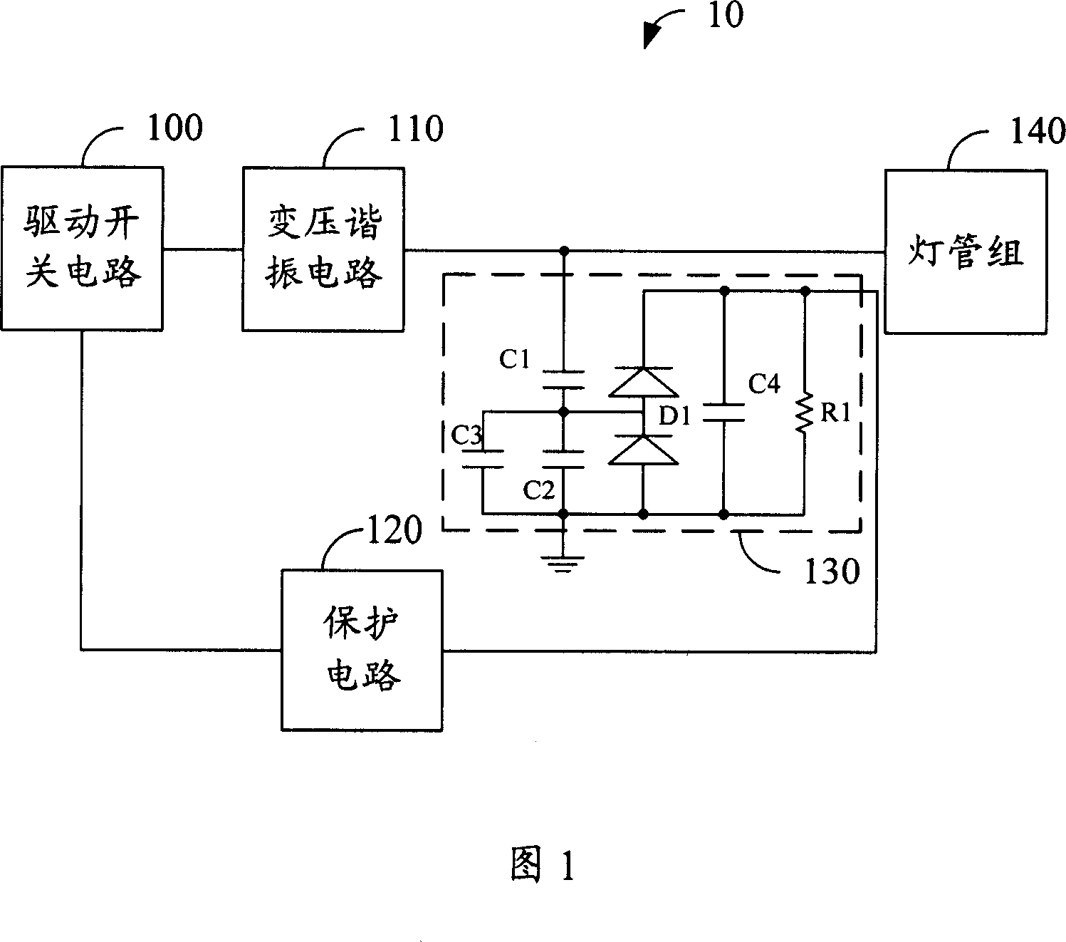
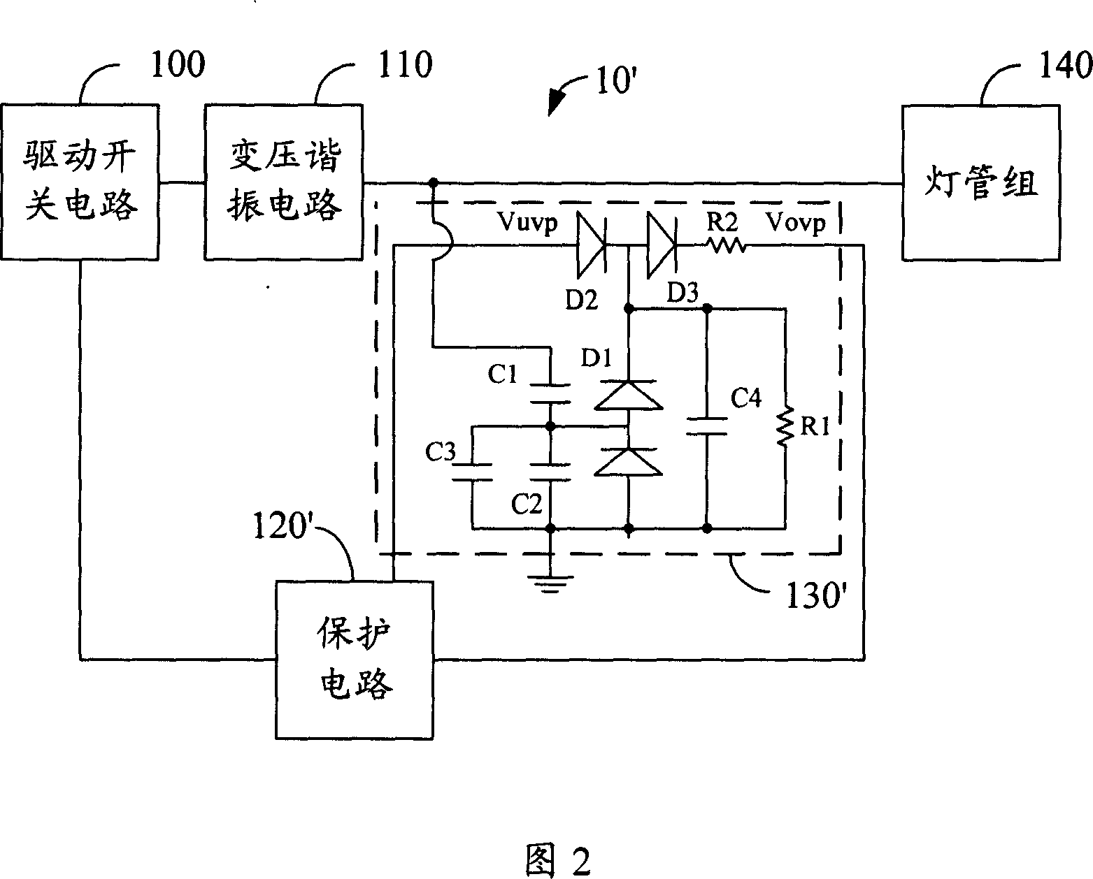
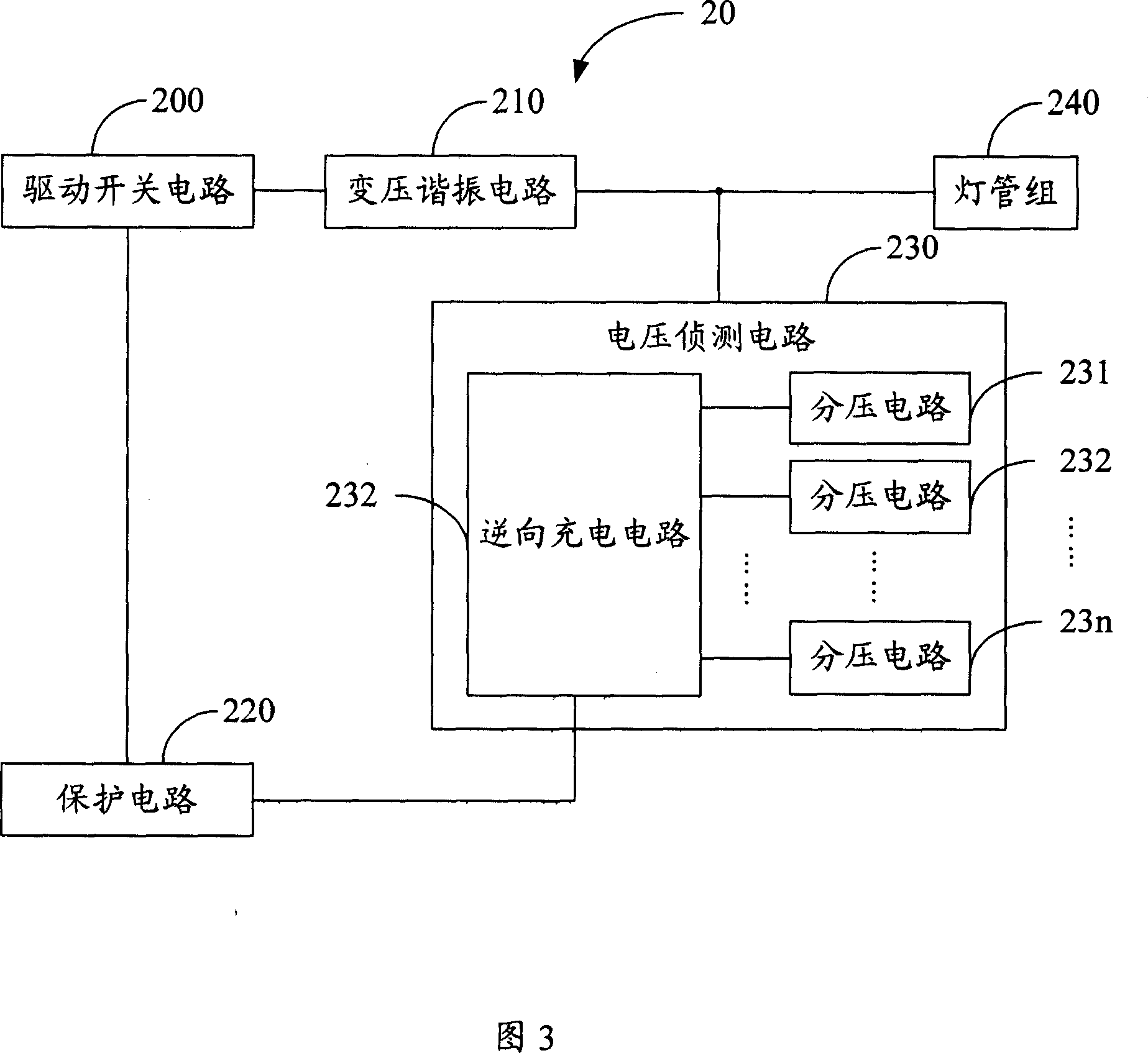
[0015] FIG. 3 is a functional block diagram of the discharge lamp driving device 20 of the present invention. The discharge lamp driving device 20 is used to drive the lamp tube group 240, wherein the lamp tube group 240 includes a plurality of discharge lamps. In this embodiment, the discharge lamp driving device 20 includes a driving switch circuit 200 , a transformer resonance circuit 210 , a protection circuit 220 and a voltage detection circuit 230 . The driving switch circuit 200 is used to convert the input DC signal into an AC signal, and output the AC signal. In this embodiment, the AC signal output by the driving switch circuit 200 is a square wave signal. The transformer resonant circuit 210 is connected with the driving switch circuit 200 for converting the AC signal output by the driving switch circuit 200 into another AC signal and outputting it to the lamp group 240 to drive the lamp group 240 . Wherein, another AC signal is a sine wave signal. The voltage de...


PUM


Abstract

This invention relates to one discharge lamp drive device to drive discharge lamp, which comprises drive switch circuit, variable resonance circuit and voltage detection circuit, wherein the drive switch circuit is to convert the input direct current signals into alternating signals; the variable resonance circuit and drive switch are connected to convert the alternating signals into other alternating signals to drive discharge lamp; the voltage detection circuit is connected between variable resonance circuit and discharge lamp composed of multiple division circuits and reverse charge circuit; the said division circuit and discharge lamp are responding for load voltage on discharge lamp.

Description

technical field [0001] The present invention relates to a discharge lamp driving device, in particular to a discharge lamp driving device applied to a liquid crystal display (liquid crystal display, LCD) backlight source module. Background technique [0002] A liquid crystal display (Liquid Crystal Display, LCD) panel uses a discharge lamp (Discharge Lamp), especially a cold cathode fluorescent lamp (Cold Cathode Fluorescent Lamp, CCFL) as a light source for a backlight (Backlight) system. Typically, the CCFL is driven by an inverter circuit (Inverter Circuit), which can supply an AC signal to the discharge lamp. When the voltage of the AC signal output by the inverter circuit is too high, it will cause damage to the discharge lamp, or even burn the discharge lamp. When the voltage of the AC signal output by the inverter circuit is too low, the discharge lamp cannot be started. Therefore, it is necessary to add a voltage detection circuit and a protection circuit in the co...

Claims


Application Information

Patent Timeline
Patent Type & Authority Applications(China)
IPC IPC(8): G09G3/34G09G3/36G09G3/20G02F1/133
Inventor 葛炽昌张志彰甘吉文
Owner HONG FU JIN PRECISION IND (SHENZHEN) CO LTD
Why Eureka
Try Eureka