Hybrid permanent magnet type electric rotating machine and manufacturing method thereof

A technology for rotating electric machines and manufacturing methods, applied to electrical components, electromechanical devices, etc., which can solve problems such as assembly difficulties, reduced reliability of rotating electric machines, and leakage, and achieve the effects of simplifying winding, easy assembly operations, and reducing costs

Active Publication Date: 2007-10-31
JAPAN SERVO CO LTD
View PDF1 Cites 17 Cited by
  • Summary
  • Abstract
  • Description
  • Claims
  • Application Information

AI Technical Summary

Problems solved by technology

[0007] However, in the motor structure disclosed in U.S. Patent No. 6,781,260, it is necessary to magnetize the two permanent magnets into opposite magnetism, and an appropriate magnetization method has not been established.
That is, the permanent magnet is magnetized by the magnetic flux reaching the saturation magnetic flux density, but in the case of magnetizing after the rotor or the motor is completed, two permanent magnets are magnetized at the same time when using a conventionally known magnetizing device using an air-core coil , since the magnetizing flux repels each other in the axial direction, the magnetization of the permanent magnet part is insufficient
In addition, when the two permanent magnets are magnetized with a set time difference at a time, the magnetic flux that magnetized the permanent magnet of one rotor unit leaks to the other rotor unit, and the leakage flux causes the other rotor unit to be magnetized. The permanent magnet is magnetized to the opposite magnetic field from the desired magnetic field, or the permanent magnet of the other rotor unit that has already been magnetized is demagnetized
Therefore, in the prior art, the rotor is assembled using components magnetized with a single magnet. However, in such a method, the permanent magnet attracts iron powder or dust during assembly, which makes assembly difficult and reduces the reliability of the completed rotating electrical machine. question

Method used


Image

  • Hybrid permanent magnet type electric rotating machine and manufacturing method thereof
  • Hybrid permanent magnet type electric rotating machine and manufacturing method thereof
  • Hybrid permanent magnet type electric rotating machine and manufacturing method thereof

Examples


no. 1 example

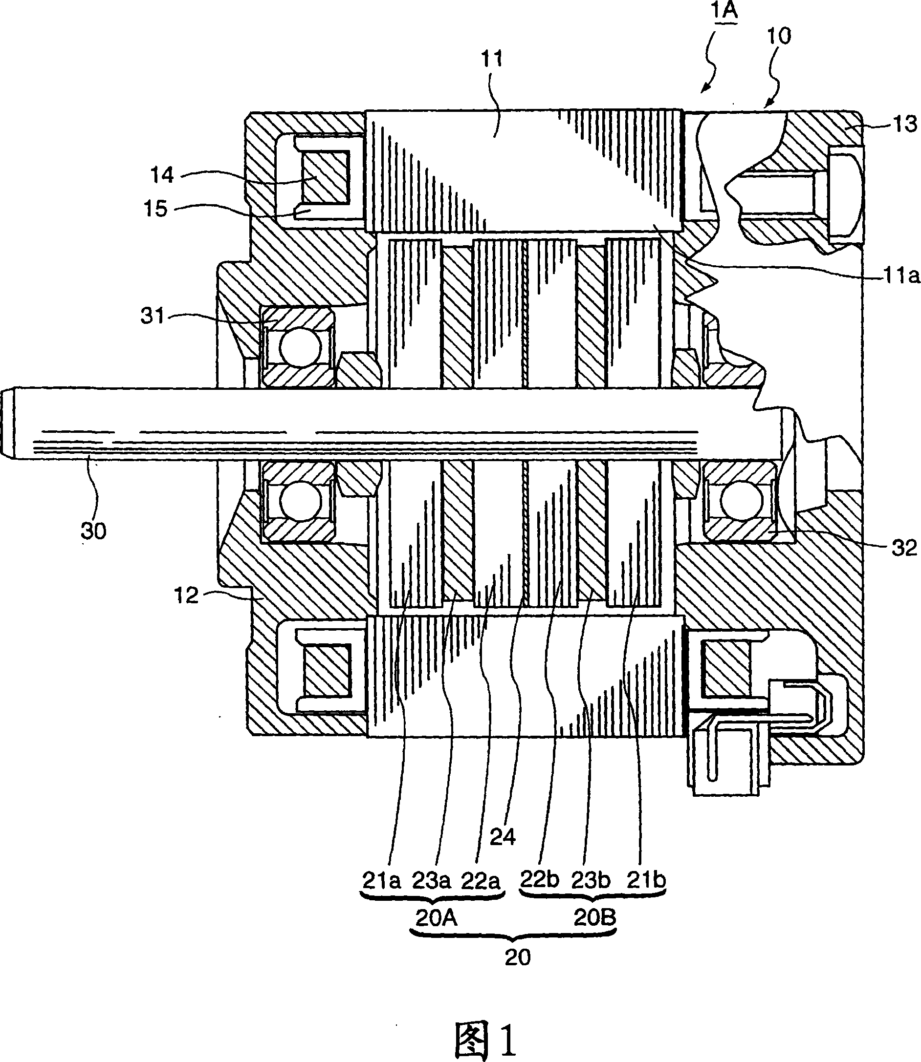
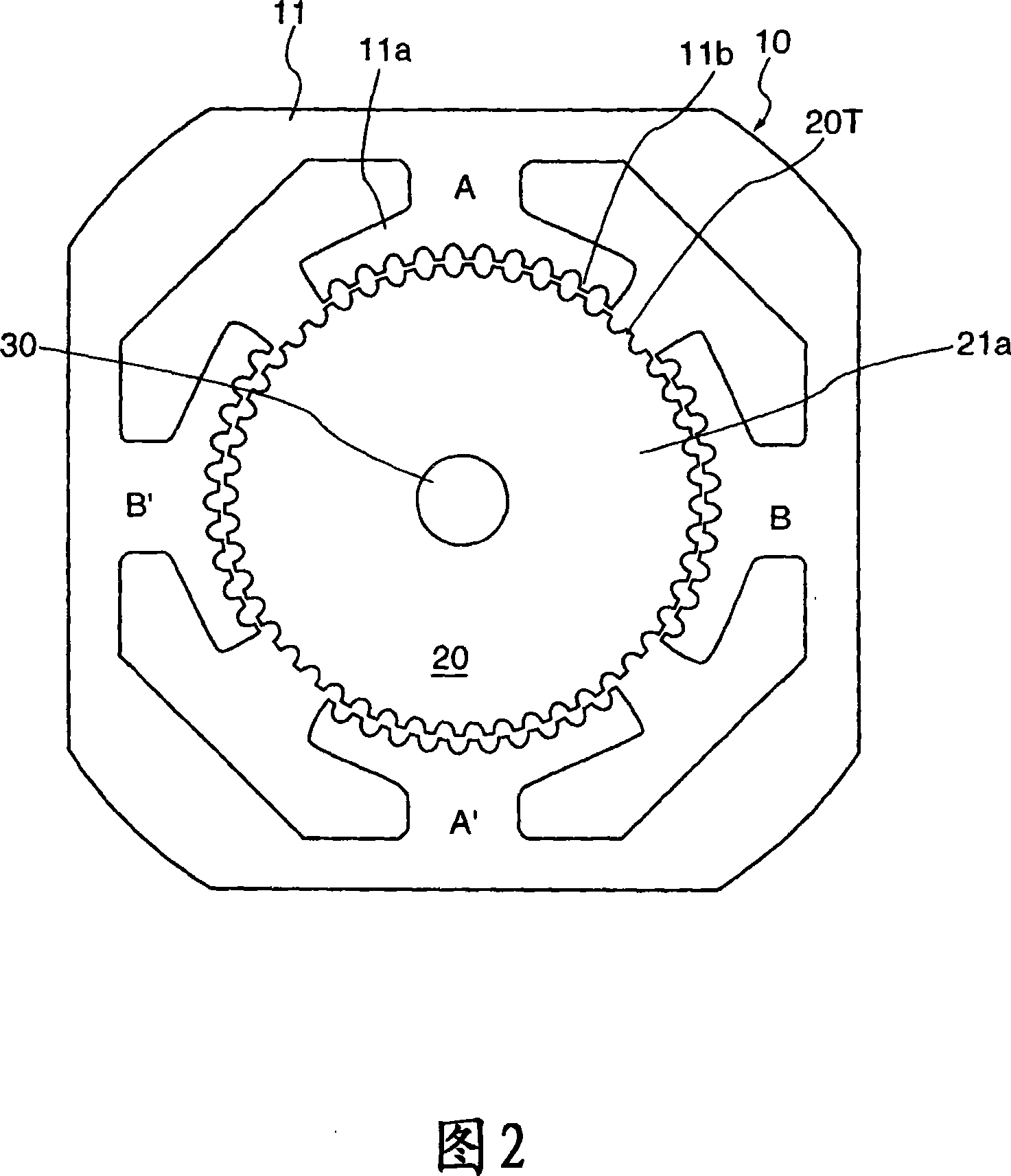
[0095] In the manufacturing method of the HB type permanent magnet rotating electrical machine of the first embodiment of the present invention, the coil 14 is wound on the main pole 11a of each stator core 11 to form the stator 10, and a pair of rotor iron cores are fixed on the rotating shaft 30. The first rotor unit 20A having a magnet material (hereinafter described using the same symbol 23a as the magnetized permanent magnet) is sandwiched between the cores 21a and 22a, and the magnet material ( The rotor 20 is constituted by the second rotor unit 20B having the same reference numeral 23b as the magnetized permanent magnet. The disposed second bracket 13 rotatably assembles the rotor 20 while ensuring a predetermined air gap with respect to the stator 10 . Thus, in a state where the magnet material is not magnetized, the structure of the stepping motor 1A is completed. Call this state an assembly.

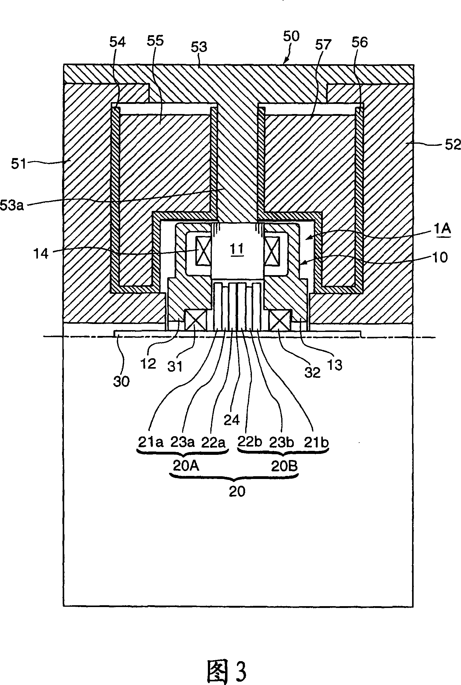
[0096] Next, this assembly is mounted on the magnetizing device 50 as s...

no. 2 example

[0109] In the manufacturing method of the HB type permanent magnet rotating electrical machine according to the second embodiment of the present invention, before assembling the rotor into the stator, after completing the construction of the rotor, the rotor is assembled into the magnetizing device as follows, to form the rotor The magnet material part of the permanent magnet is magnetized.

[0110] That is, as shown in FIG. 4 , the first rotor unit 20A, which clamps the magnet material 23a between the pair of rotor cores 21a, 22a, and the first rotor unit 20A clamped between the pair of rotor cores 21b, 22b, are fixed on the rotating shaft 30. The second rotor unit 20B holding the magnet material 23b constitutes the rotor 20, and the rotor 20 is mounted on the magnetizing device 60 to magnetize the two magnet materials 23a, 23b to form a permanent magnet.

[0111] The magnetizing device 60 of the second embodiment has a cylindrical first yoke 61 and a second yoke 62 arranged ...

no. 3 example

[0123] Compared with the case of the first embodiment, the manufacturing method of the HB type permanent magnet rotating electrical machine according to the third embodiment of the present invention is that the magnets on the rotor side are filled in the state where the rotor is assembled into the stator. The point of magnetism is the same, but the point of using the magnetizing device 70 shown in FIG. 5 as the magnetizing device is different.

[0124] That is, the stator 10 is formed by winding the coil 14 on the stator core 11, and the first rotor unit 20A, which sandwiches the magnet material 23a between the pair of rotor cores 21a and 22a, is fixed on the rotating shaft 30, and the pair of The second rotor unit 20B with the magnet material 23b sandwiched between the rotor cores 21b and 22b constitutes the rotor 20, and the first bracket 12 disposed outside the first rotor unit 20A and the second rotor unit disposed outside the second rotor unit 20B constitute the rotor 20. ...


PUM


Abstract

A stator is constructed by winding excitation coils around respective main poles in a hybrid permanent magnet type electric rotating machine. A rotor is constructed by fixing a first rotor unit, which consists of a pair of rotor cores and a magnetic material sandwiched between the rotor cores, and a second rotor unit, which has the same construction as the first rotor unit, to a rotation shaft. The rotor is assembled to the stator to form an assembled body. The magnet material of the first rotor unit is magnetized in the axial direction by a magnetizing flux passing through a half of the assembled body in the axial direction. The magnet material of the second rotor unit is magnetized in the axial direction in an opposite polarity by a magnetizing flux passing through the remaining half of the assembled body in the axial direction.

Description

technical field [0001] The present invention relates to a hybrid (hereinafter abbreviated as HB) permanent magnet rotary motor used in OA equipment for processing images of facsimile machines, inkjet printers, laser printers, copiers, etc., and a manufacturing method thereof. Background technique [0002] 14 and 15 show a conventional 2-phase HB stepping motor. FIG. 14 is a longitudinal section, and FIG. 15 is a front view showing the relationship between the rotor core and the stator core. This stepping motor 100 has a stator 110 and a rotor 130. The stator 110 has a stator core 111 having two phases and eight main poles. The rotor 130 is fixed to a rotating shaft 120 rotatably supported inside the stator. The stator 110 is constituted by sandwiching a stator core 111 formed of laminated silicon steel plates from both sides in the axial direction by brackets 112 and 113 formed of non-magnetic materials. The excitation coil 114 wound on the bobbin 115 is wound. On the stat...

Claims


Application Information

Patent Timeline
Patent Type & Authority Applications(China)
IPC IPC(8): H02K37/00H02K37/14
Inventor 坂本正文小林亨畔上昌彦茂木康彰加藤隆弥大岩昭二松田靖夫大西和夫福岛忠田中宣基
Owner JAPAN SERVO CO LTD
Why Eureka
Try Eureka