Medical radiotherapy assembly

A radiation therapy and radiation source technology, applied in the field of medical radiation therapy devices, can solve problems such as inaccuracy, difficulty in precise positioning, adverse effects of radiation therapy effects, etc., and achieve cost-saving effects

Inactive Publication Date: 2007-10-31
VARIAN MEDICAL SYST PARTICLE THERAPY
View PDF1 Cites 13 Cited by
  • Summary
  • Abstract
  • Description
  • Claims
  • Application Information

AI Technical Summary

Problems solved by technology

[0006] Changes in the tumor's position between the time of diagnosis and the time of each irradiation can adversely affect the efficacy of radiation therapy
The orientation of the patient in the isocenter with the aid of the markers is also subject to inaccuracies
Even if the tumor location is confirmed directly before radiation, it is difficult to pinpoint precisely because the patient moves from the shooting position to the irradiation position

Method used


Image

  • Medical radiotherapy assembly
  • Medical radiotherapy assembly
  • Medical radiotherapy assembly

Examples


Embodiment Construction

[0025] Parts with the same effect in the figures are provided with the same reference symbols.

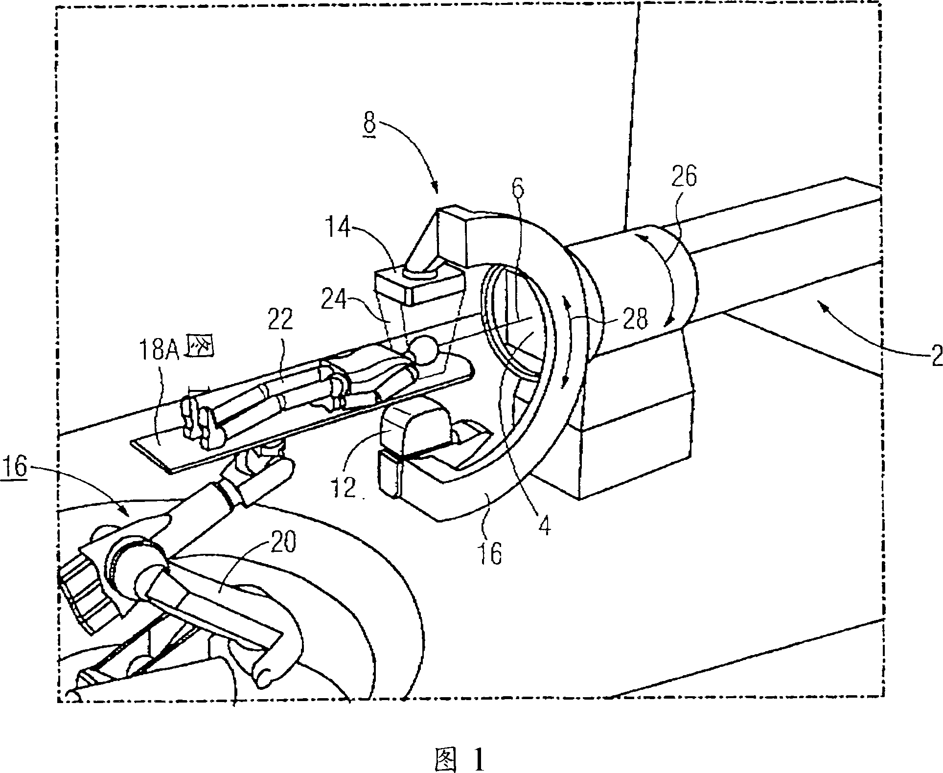
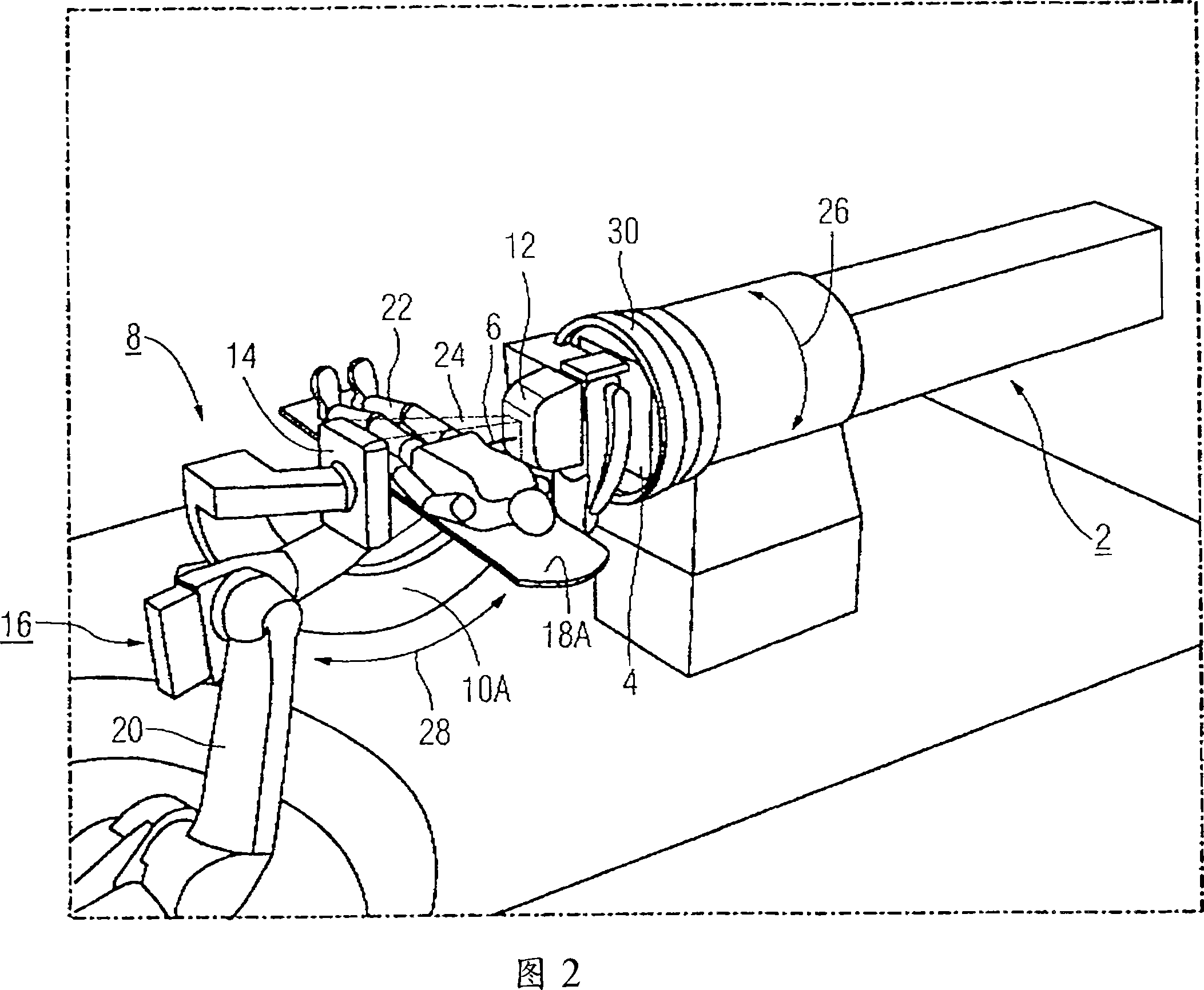
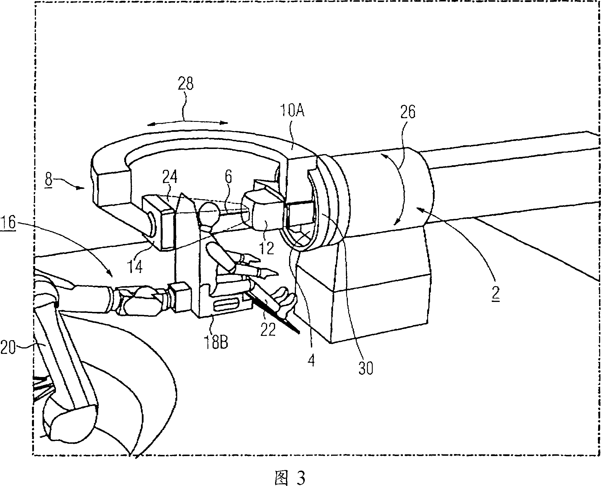
[0026] In all embodiments, the medical radiation therapy device includes a particle accelerator, referred to below as a particle emitter, for generating a particle beam composed of heavy ions. The particle emitter comprises a radiation tube 2 which has a front emission window 4 from which particle radiation 6 is emitted at a predetermined position during operation. The radiation tube 2 with the emission window 4 is fixed in space. As an alternative to the exemplary embodiment shown, a plurality of fixed emission windows 4 are arranged spatially at defined angles.

[0027] Furthermore, the device has an x-ray diagnostic device 8 with support arms 10A, 10B on which an x-ray source 12 and an x-ray detector 14 are each arranged at opposite positions.

[0028]Furthermore, the radiotherapy system includes a patient support device 16 with a patient couch 18 which can be moved in a contr...


PUM


Abstract

The invention relates to a mold for manufacturing holders such as crates, comprising at least two mold parts, moveable relative to each other in a first direction of movement, in which at least one mold cavity is included, the mold cavity being provided on at least side with a wall part moveable in a second direction of movement movable between a first, retracted position and a second position moved forward, while the mold cavity, with side wall part in the second position, is in a desired poduct forming position and with said wall part in the first position has a volume greater than with said wall part in the second position, while the first and the second direction of movement mutually include an angle.

Description

technical field [0001] The invention relates to a medical radiotherapy device, for example for treating tumors. Background technique [0002] In radiation therapy with heavy ions, the tumor is bombarded with accelerated particles. In this case, the particle accelerator produces a particle beam with a spatially fixed beam emission. For the treatment to take place, the patient must be brought to a predetermined precise position, to be precise, so that the tumor is located at the so-called isocenter of the particle beam. Depending on the position of the tumor in the body, different irradiation positions (fields) are used for the patient, for example, the patient is positioned in front of the particle beam device in a supine or seated position. [0003] In the preparatory phase of radiotherapy it is therefore required to determine the tumor's position as precisely as possible. Imaging diagnostic methods are used for this. For X-ray diagnostic devices see, for example, DE 189...

Claims


Application Information

Patent Timeline
IPC IPC(8): A61N5/10
CPCA61N5/1069A61N5/1049A61B6/4458A61N5/1082A61N2005/1061A61N5/10A61B6/4464
Inventor 克劳斯·赫尔曼
Owner VARIAN MEDICAL SYST PARTICLE THERAPY
Why Eureka
Try Eureka