
Heat exchanger

A technology of heat exchangers and heat sinks, applied in heat exchange equipment, indirect heat exchangers, heat exchanger types, etc., can solve problems such as damage to the outer edge of heat sinks, deformation of heat sinks, difficulty in condensing water, etc., and achieve flow Smoothness, preventing deformation of ribs, and increasing aggregation

Inactive Publication Date: 2007-10-31
DAIKIN IND LTD
View PDF1 Cites 0 Cited by
  • Summary
  • Abstract
  • Description
  • Claims
  • Application Information

AI Technical Summary

Problems solved by technology

[0007] However, in the above-mentioned conventional heat exchangers, when the grooves are formed too close to the outer edge of the fins, or too close to the insertion holes formed on the fins for the insertion of heat transfer tubes, there are holes formed in the fins. Deformation of the edge of the groove or deformation of the groove itself
In addition, due to the deformation of the above-mentioned groove, condensed water can be accumulated in the groove, so that there is a problem that the condensed water is difficult to flow downward in the vertical direction.
In addition, the edges of the heat sinks where the grooves are formed are deformed into wavy shapes, and there is a problem that people are injured by the wavy outer edges of the heat sinks.

Method used


Image

  • Heat exchanger
  • Heat exchanger
  • Heat exchanger

Examples


Embodiment Construction

[0049] The present invention will be described in detail below by means of illustrations.

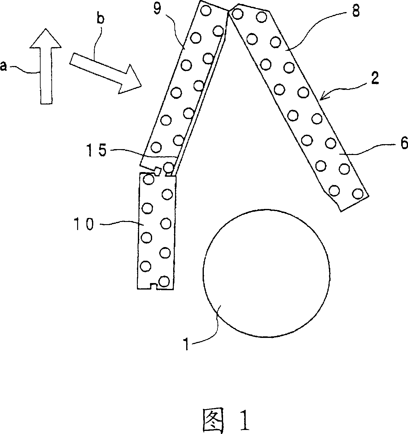
[0050]Fig. 1 is a schematic sectional view of an air conditioner using a heat exchanger according to an embodiment of the present invention. In Fig. 1, 1 is a blower fan, and 2 is a heat exchanger. In addition, in FIG. 1 , arrow a indicates that the heat exchanger is arranged vertically upward in the air conditioner in use, and arrow b indicates the flow direction of wind as a heat transfer medium. In FIG. 1 , for the sake of simplification, the case for accommodating the blower fan 1 and the heat exchanger 2 and the like are omitted.

[0051] In this air conditioner, the blower fan 1 is rotated, and the air sucked in via the heat exchanger 2 is blown out from an air outlet not shown.

[0052] The heat exchanger 2 has a fan 6 and heat transfer tubes (not shown). The plurality of fans 6 are arranged at predetermined intervals in a direction perpendicular to the paper surface in FIG. 1...


PUM


Abstract

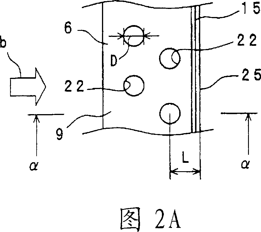
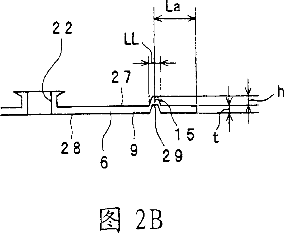
A plurality of through holes (22) are formed on a fin (6) for penetrating heat exchanger tube, and a rib (15) extending substantially parallel to an external edge (25) of the fin (6) is formed on the fin (6). The rib (15) is arranged closer to the side of the external edge (25) than all the through holes (22). When the inner diameter of the through holes (22) is D[mm], a distance between the center of the through hole (22) closest to the rib (15) and the external edge (25) is L[mm], a distance between the center of the rib (15) and the external edge (25) is La[mm], the width of the rib (15) is LL[mm], the plate thickness of the fin (6) is t[mm], and the height of the rib (15) is h[mm], the rib (15) satisfying the following inequalities is formed on the fin (6); 0.4<La<(L-D / 2-0.5), 0.15<LL<0.5, 0.05<t<0.15, and 0.5t<h<2.5t.

Description

technical field [0001] The present invention relates to a heat exchanger, in particular to a heat exchanger suitable for use in refrigeration devices such as air conditioners. Background technique [0002] Conventionally, as a heat exchanger, there is a heat exchanger described in JP-A-2000-35296. [0003] The heat exchanger has a plurality of fins and a plurality of heat transfer tubes overlapping at predetermined intervals. [0004] The plurality of heat transfer tubes are inserted through the plurality of cooling fins at predetermined intervals. [0005] Grooves are formed at both ends in the width direction of the heat sink, and the grooves extend in a direction along the outer edge of the heat sink in the longitudinal direction. The groove guides the condensed water droplets generated on the surface of the heat sink from above to below. [0006] In the conventional heat exchanger described above, the condensed water droplets generated on the surface of the fins are g...

Claims


Application Information

Patent Timeline
Patent Type & Authority Applications(China)
IPC IPC(8): F28D1/047F28F1/32F28F1/26F24F1/0067
CPCF28F1/32F28F17/005F28F2225/06F24F1/0059F24F1/0067F28D1/047F28F1/26
Inventor 北泽昌昭平良繁治
Owner DAIKIN IND LTD
Learn More