Vacuum processing chamber for very large area substrates

A technology for vacuum processing chamber and substrate processing, which is used in coating, gaseous chemical plating, discharge tube, etc.

Inactive Publication Date: 2007-10-31
东电电子太阳能股份公司
View PDF1 Cites 5 Cited by
  • Summary
  • Abstract
  • Description
  • Claims
  • Application Information

AI Technical Summary

Problems solved by technology

Furthermore, reactors reach larger and larger sizes and must comply with increasing deformation and expansion issues

Method used


Image

  • Vacuum processing chamber for very large area substrates
  • Vacuum processing chamber for very large area substrates
  • Vacuum processing chamber for very large area substrates

Examples


Embodiment Construction

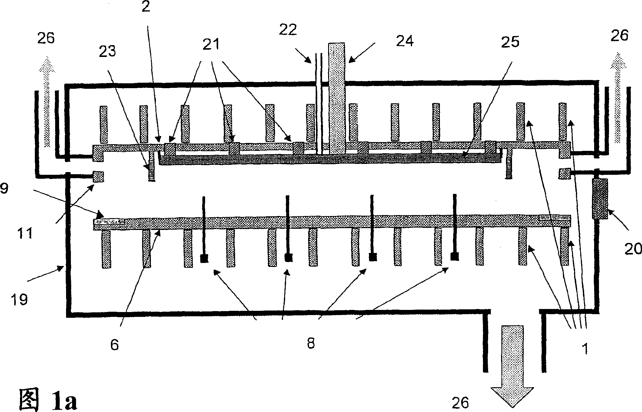
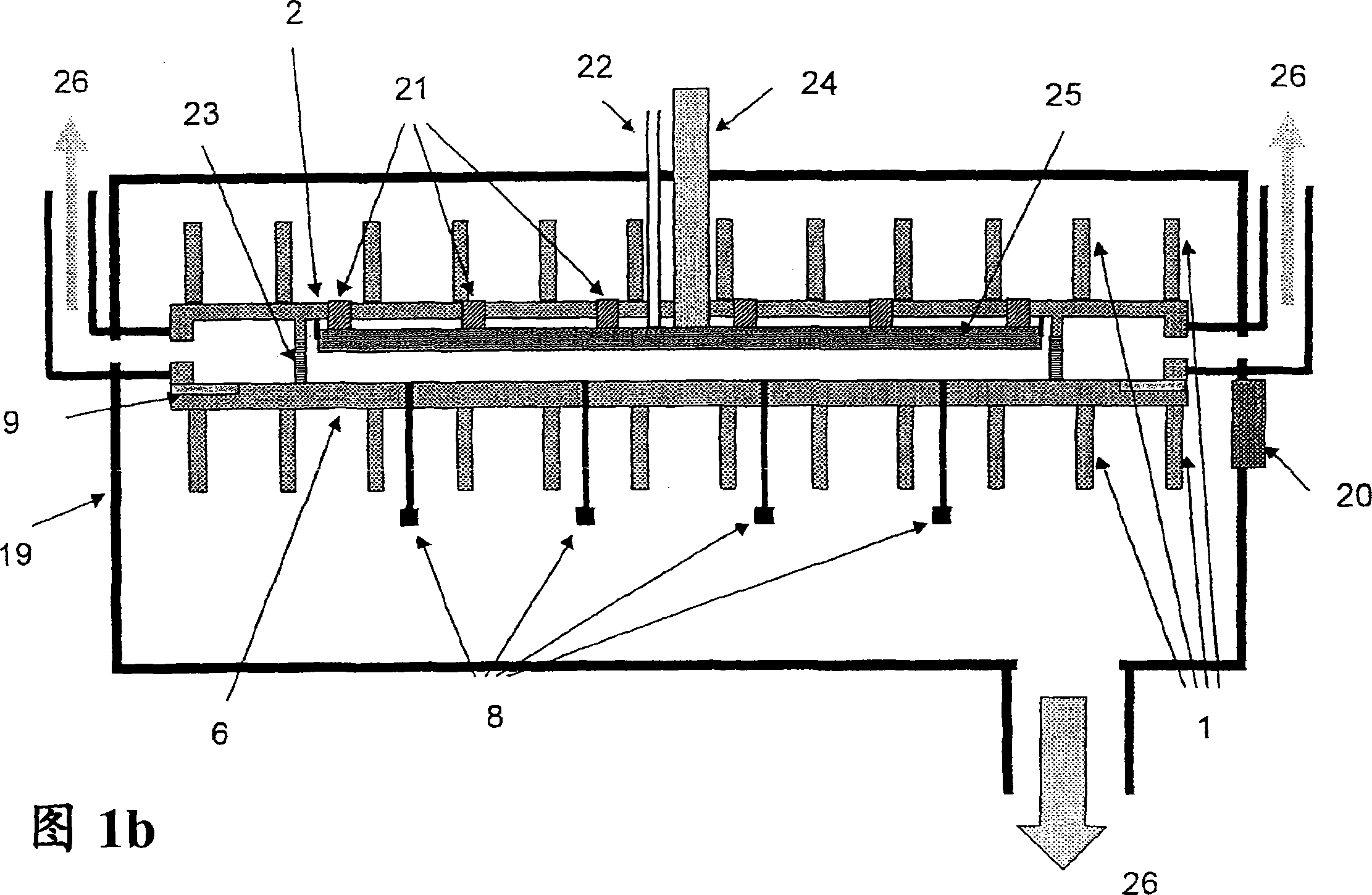
[0046] Therefore, the present invention is based on a new reactor concept. The reactor is divided into two parts: the reactor bottom 6 and the reactor top 2 (see Figure 1). The reactor top 2 is preferably connected to an external vacuum process chamber 19 via a reinforcement 1 (connection not shown in Figure 1 ). The reactor bottom 6 (or bottoms in the case of a single external chamber multi-reactor system) is vertically movable such that a gap is opened between the reactor side wall 11 and the sealing plate 9 . When the reactor is fully opened, the gap widens and the lifting pin 8 starts to protrude. The loading fork (not shown in FIG. 1 ) can then place the substrate on the lift pins for loading, or retract the substrate from the lift pins 8 by lifting the substrate through the door valve 20 from below. This "inverted shoebox" type of opening has the main advantage that the height of the reactor wall 11 and thus the corresponding plasma gap can be relatively small. If the...


PUM


Abstract

A plasma reactor for PECVO treatment of large-size substrates according to the invention comprises a vacuum process chamber as an outer chamber and at least one inner reactor with an electrode showerhead acting as RF antenna, said inner reactor again comprising a reactor bottom and a reactor top, being sealingly connected at least during treatment of substrates in the plasma reactor and separated at least during loading / unloading of the substrates. Further embodiments comprise a sealing for said reactor to / bottom and a suspender for the RF antenna / electrode showerhead.

Description

[0001] The present invention relates to a vacuum processing apparatus for very large-area substrates, especially a PECVD processing chamber (respectively an internal reactor) with a planar deviation compensation mechanism. Background of the invention [0002] The present invention relates generally to large area PECVD processing chambers and in particular to such chambers which are themselves reenclosed within a second surrounding vacuum chamber. This "box-in-box" (Plasma Box TM ) are known in the art and described in US Patent No. 4,798,739. The main advantage of this "box within a box" is that a lower pressure can be maintained in the outer airtight chamber than in the inner reactor chamber, so that controlled gas flow can be maintained from the inner chamber to the outer chamber ("differential pumping"). A further advantage of this "box-in-box" system is that the internal chamber can be kept at a constant process temperature, typically around 250-350°C (isothermal reactor)...

Claims


Application Information

Patent Timeline
Patent Type & Authority Applications(China)
IPC IPC(8): H01J37/32C23C16/509C23C16/458
CPCC23C16/4409H01J37/32082H01J2237/3325C23C16/54H01J37/32458C23C16/509C23C16/00
Inventor P·埃恩格L·德劳内伊S·约斯特M·埃亚考比
Owner 东电电子太阳能股份公司
Why Eureka
Try Eureka