
Energy-saving combustor

The technology of a combustion device and a throttle valve, which is applied in the field of combustion devices, can solve problems such as complex structures, and achieve the effect of firm installation, simple structure, and guaranteed combustion

Inactive Publication Date: 2007-11-07
王强
View PDF2 Cites 0 Cited by
  • Summary
  • Abstract
  • Description
  • Claims
  • Application Information

AI Technical Summary

Problems solved by technology

The device scheme can solve the problem of sufficient gasification and complete combustion without residual liquid; but its structure is relatively complicated

Method used


Image

  • Energy-saving combustor
  • Energy-saving combustor

Examples


Embodiment Construction

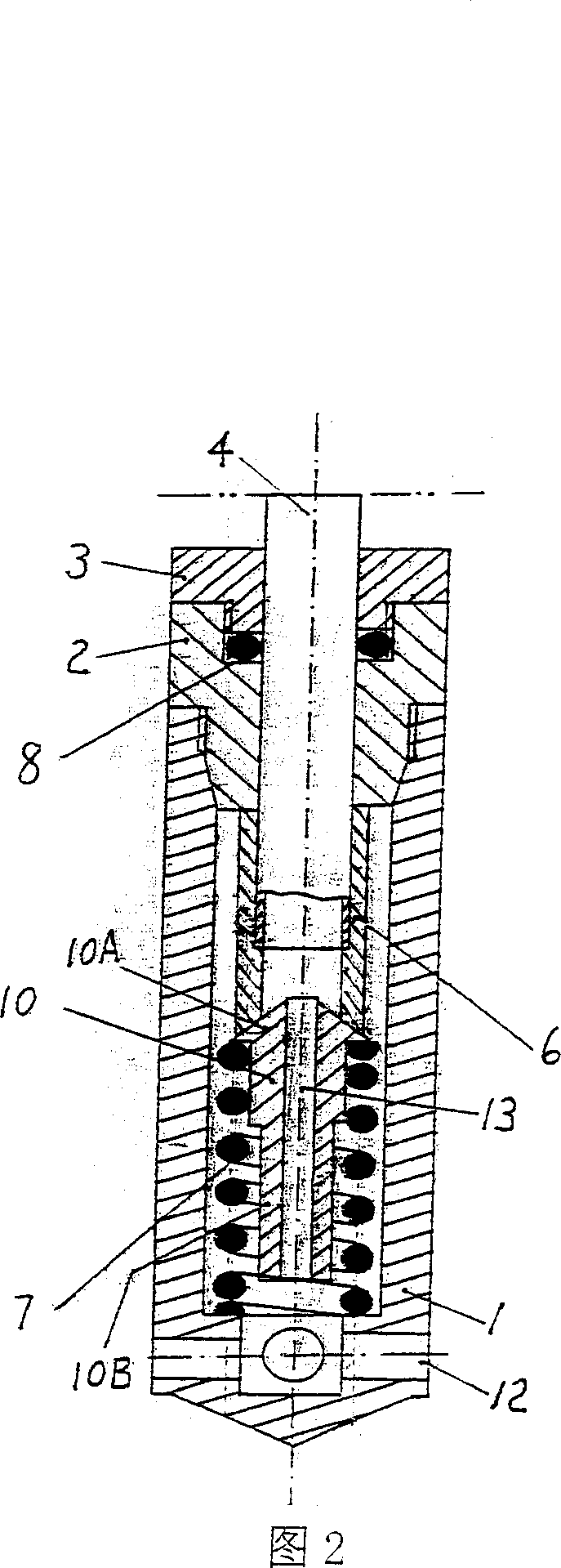
[0024] Fig. 1, 2 show the structure schematic diagram that energy-saving combustion device of the present invention is contained in container 15, and container 15 among the present embodiment is liquefied petroleum gas steel cylinder, and the top of steel cylinder is equipped with angle valve 14, is used for drawing the gas that is burned .

[0025] The energy-saving combustion device of the present invention comprises an upper joint 5, a lower joint 1 and a mixing tube 4 whose two ends are respectively connected to the upper and lower joints,

[0026] The lower end of the mixing tube 4 extends into the inner cavity of the lower joint 1;

[0027] In the inner cavity of the lower joint 1, a throttle valve 10 and a spring 7 are installed. One end of the spring 7 presses against the bottom of the inner cavity of the lower joint 1, and the other end acts on the inner cavity of the lower joint 1. On the throttle valve 10, the throttle valve 10 is pressed against the lower end of t...


PUM


Abstract

An energy saving burn device includes the up joint, the down joint and the mixing pipe which the two ends are connected with the up and down joints. The character is in that: the down end of the mixing pipe extends to the inner hollow of the down joint; the inner hollow of down joint is installed with the throttle and spring; the one end of the spring is at the bottom of the down joint inner hollow, the other acts on the throttle which presses on the down end of the mixing pipe; the throttle has the channels which connect the down joint hollow and the mixing pipe. The energy saving burn device has the simple structure and burn the residue liquid without dark smoke, so it is proper for every liquid gas container.

Description

technical field [0001] The invention relates to a combustion device, in particular to an energy-saving combustion device. Background technique [0002] When people use the liquefied gas stored in the pressure vessel for combustion, in the container, because the upper part of the lighter liquefied gas is first discharged for combustion, the remaining heavier liquefied gas accumulates in the bottom of the pressure vessel in the form of liquid; When the liquefied gas in the pressure vessel decreases, its pressure decreases, and the residual liquid accumulated at the bottom of the pressure vessel cannot be discharged, resulting in the accumulation of residual liquid at the bottom of the pressure vessel, especially in winter; the accumulated residual liquid not only wastes energy but also makes the next Insufficient weight for the first fill. [0003] In the Chinese patent application CN200420023983, a liquefied gas raffinate burner is disclosed, which is composed of a wire, an ...

Claims


Application Information

Patent Timeline
Patent Type & Authority Applications(China)
IPC IPC(8): F17C7/04
Inventor 王东成
Owner 王强
Learn More