
Load switch operation axle link lock device

A load switch and interlocking device technology, applied in the field of electric power, to achieve the effects of flexible mechanical transmission, convenient operation, and simple interlocking structure

Inactive Publication Date: 2007-11-07
BEIHAI GALAXY SWITCH DEVICES
View PDF0 Cites 3 Cited by
  • Summary
  • Abstract
  • Description
  • Claims
  • Application Information

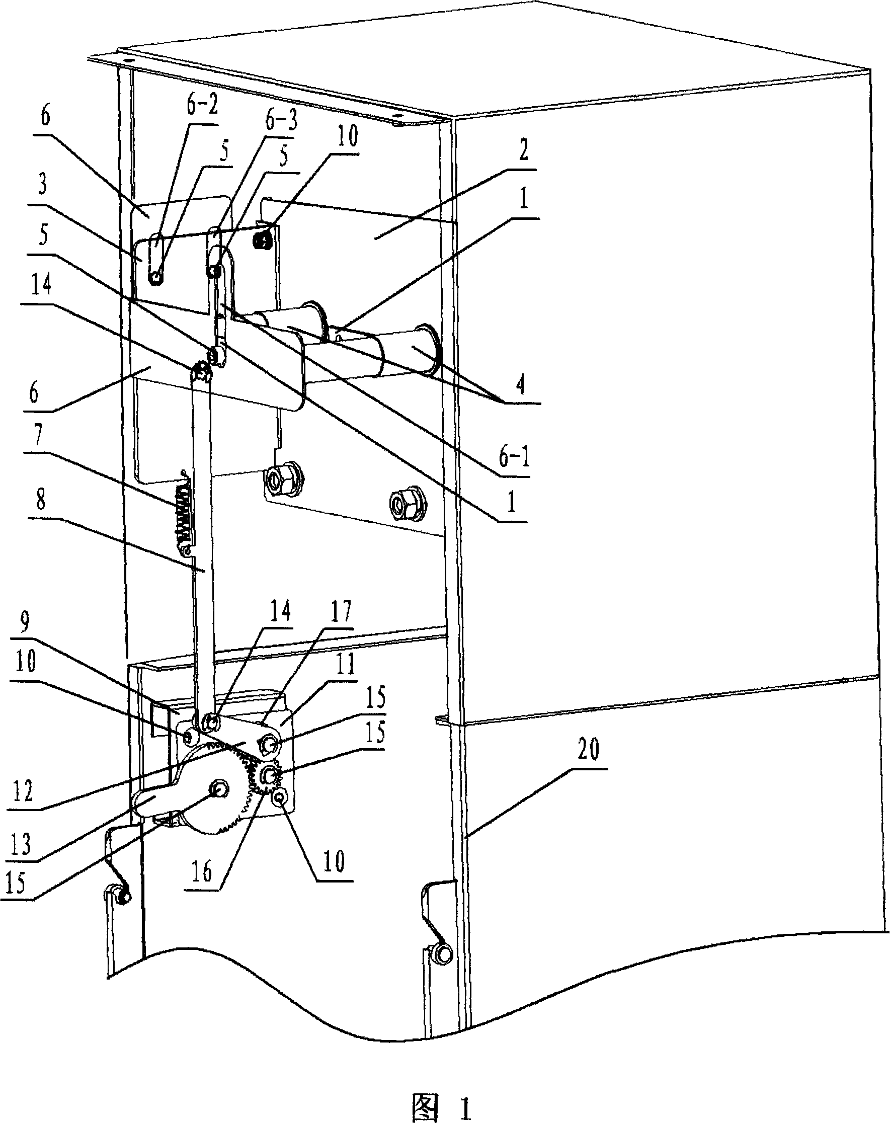
AI Technical Summary

Problems solved by technology

[0003] The purpose of this invention is to provide a load switch operating shaft interlocking device to overcome the shortcomings of the current load switch operating shaft interlocking

Method used


Image

  • Load switch operation axle link lock device
  • Load switch operation axle link lock device
  • Load switch operation axle link lock device

Examples


Embodiment Construction

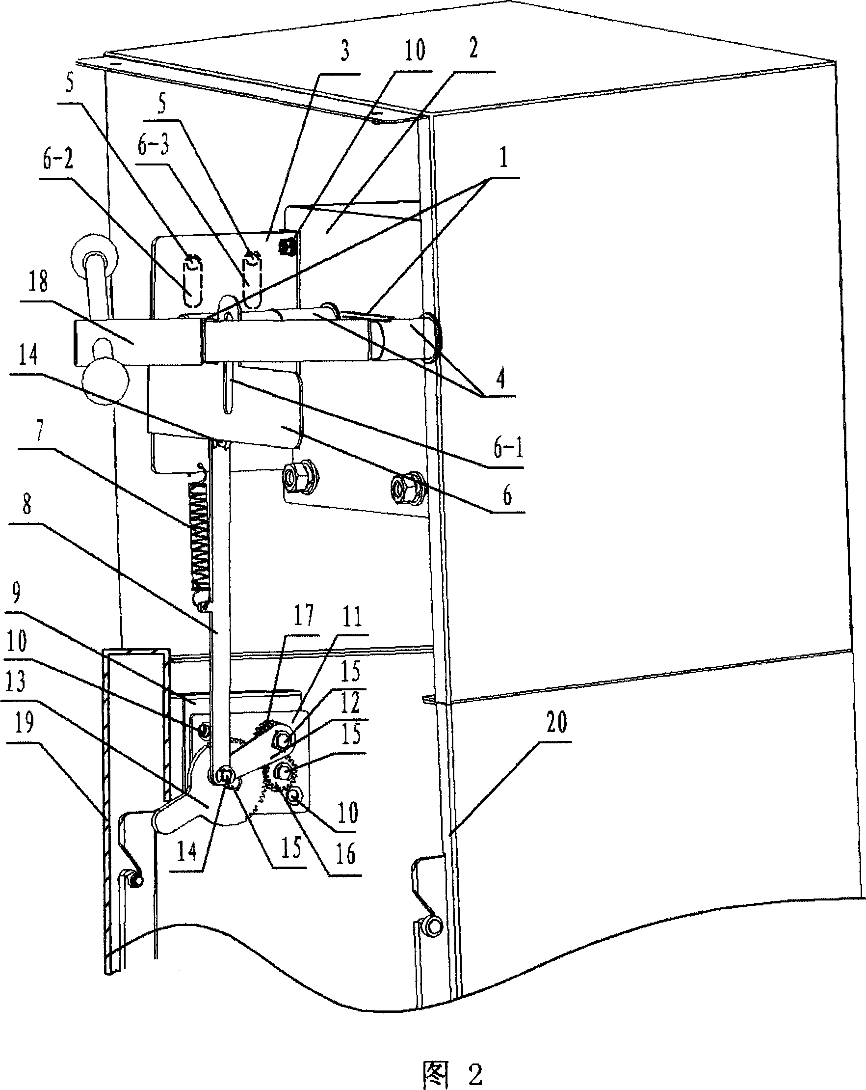
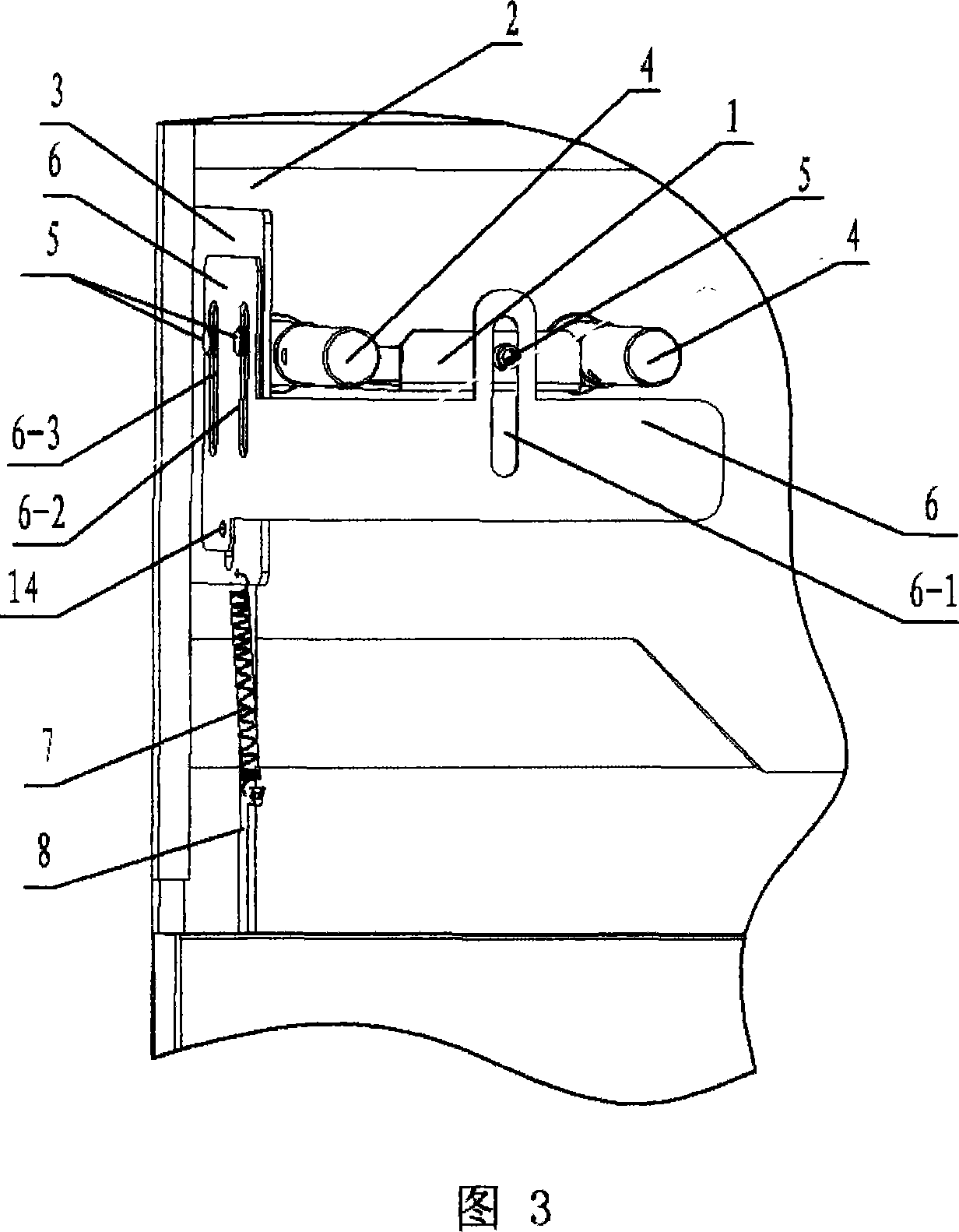
[0010] The purpose of the load switch operating shaft interlocking device of the present invention is that when the load switch lower door leaf 19 is closed, the operating handle 18 can be inserted into the mechanism operating shaft 4 for operation; when the lower door leaf 19 is opened, the operating mechanism operating shaft 4 and the right-angle interlocking plate are not allowed. 6 blocks the mechanism operating shaft 4 so that the operating handle 18 cannot be inserted and cannot be operated.

[0011] See accompanying drawing 1. Fig. 1 is a perspective view of the structure of the lower door 19 of the present invention when it is opened. It can be seen from Figure 1 that the load switch operation shaft interlocking device includes a fixed bent plate 1, a mechanism front plate 2, a fixed plate 3, a tension spring 7, a connecting rod 8, a side bent plate 9 of the chassis, a gear fixed plate 11, and a crank arm 12. Movable pin 14, fixed pin 15, chassis lower door leaf 19, c...


PUM


Abstract

This invention relates to an interlocking device of a load switch operation shaft including a fixed angle plate, a unit front plate, a fixed plate, a tension spring, a connecting rod, an angle plate at the side of a chassis, a gear fixed plate, a turning arm, a mobile pin, a fixed pin, a lower door fan of the chassis and a shell, in which, a big gear with a long handle, a transition gear and a small gear are set on the fixed plate of the gear, which are fixed on the gear fixed plate by the fixed pin and rotate on the pin forced by power, the angle arm and the small gear are matched to rotate coaxially with the fixed pin, the big gear is matched with the transition gear, which is matched with the small gear fixed at an end of the angle arm with the fixed pin, and the other end of the angle arm is connected with one end of the connecting rod via the mobile pin and the other end is connected with the right-angle interlocking plate by the mobile pin.

Description

technical field [0001] The invention belongs to the field of electric power technology, and in particular relates to the design and manufacture of a load switch operating shaft interlocking device used on a ring network cabinet. technical background [0002] In the power system, the load switch used on the ring network cabinet, in order to make the power run safely, the operating regulations stipulate that when the lower door leaf of the load switch cabinet is opened, the load switch is not allowed to be operated. Only after the lower door leaf of the load switch is closed, Only then can the load switch be operated. Regrettably, when the lower door leaf is closed, the interlocking device that can realize the interlocking function by using its own gravity has not yet been put on the market. If a kind of gear transmission is designed and manufactured, the long handle of the gear is pressed down by the gravity of the lower door leaf, and the long handle gear drives other gear ...

Claims


Application Information

Patent Timeline
Patent Type & Authority Applications(China)
IPC IPC(8): H01H31/04H01H31/06H01H9/20H01H9/22
Inventor 陶春丽刘桂华
Owner BEIHAI GALAXY SWITCH DEVICES
Learn More