Ultrasmall type voice coil motor

A voice coil motor and current technology, applied in the direction of electrical components, electromechanical devices, electric components, etc., can solve the problems of limited application, achieve the simplification of the installation process, reduce the axial size of the device, and reduce the radial and axial dimensions Effect

Inactive Publication Date: 2010-09-01
YIXING GUIXIN MAGNETOELECTRIC HI TECH
View PDF2 Cites 0 Cited by
  • Summary
  • Abstract
  • Description
  • Claims
  • Application Information

AI Technical Summary

Problems solved by technology

The above defects of the prior art have largely limited its application in the field of autofocus camera modules for mobile phones and notebook computers

Method used


Image

  • Ultrasmall type voice coil motor
  • Ultrasmall type voice coil motor
  • Ultrasmall type voice coil motor

Examples


Embodiment Construction

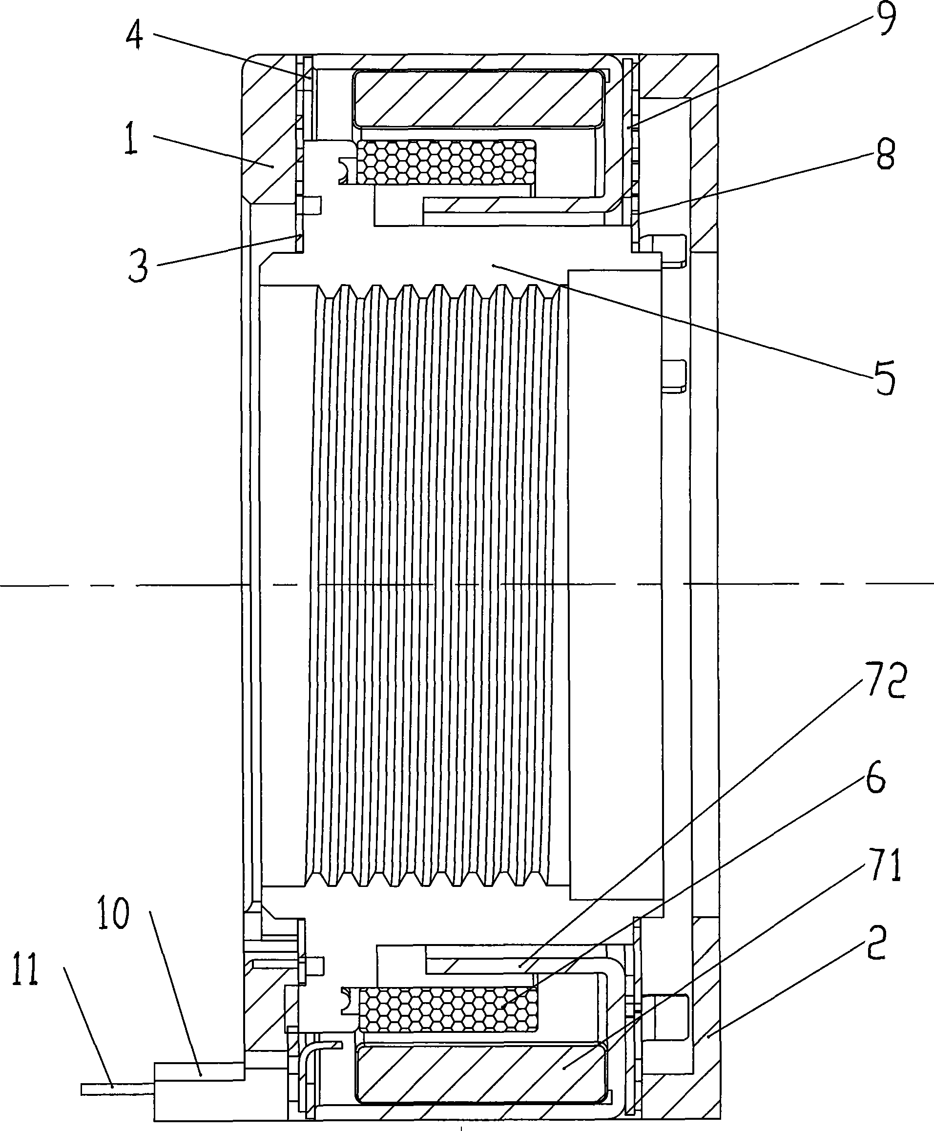
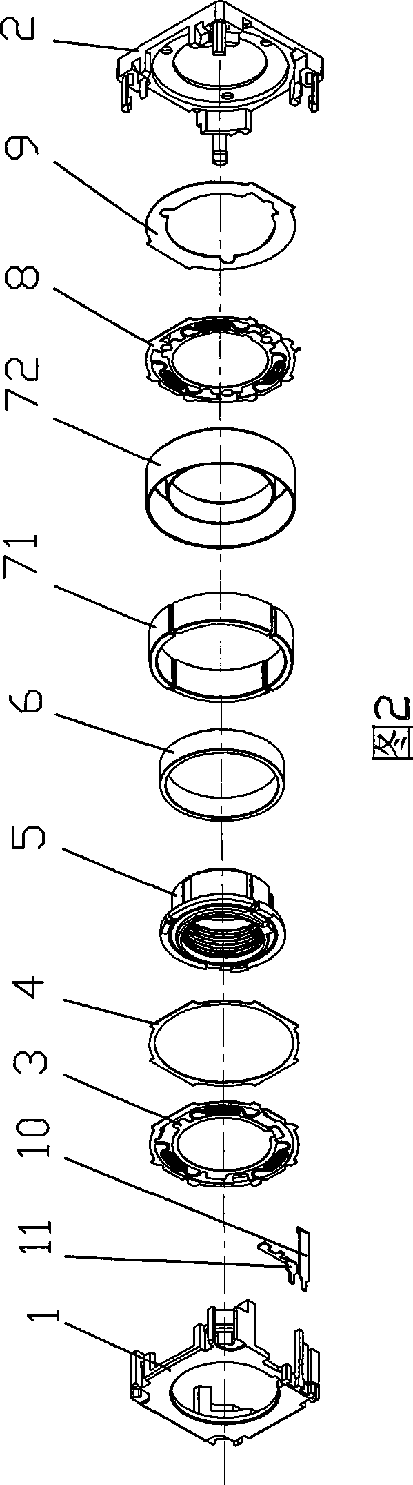
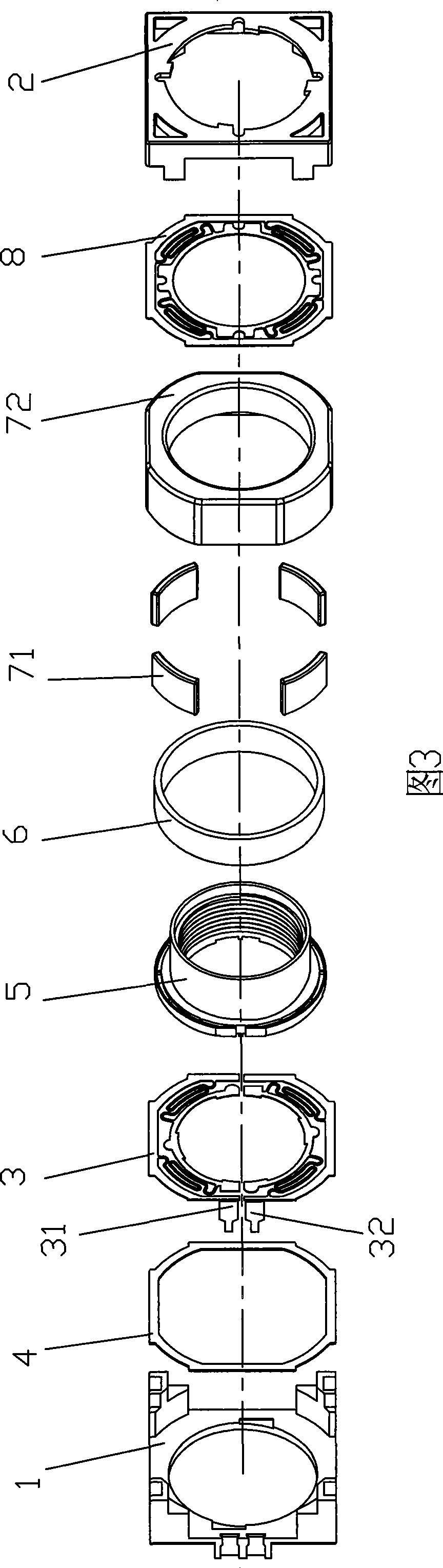
[0025] Attached below Figure 3-9 , to describe a specific embodiment of the present invention. Such as image 3 As shown, the present invention includes: front and rear cover plates 2,1, motion carrier 5, conductive coil 6, permanent magnet unit 7 and split front and rear spring pieces 8,3. The insulating sheet 4 is disposed between the metal case 72 and the rear spring 3 . Four pieces of 40-degree arc-shaped permanent magnets 71 are arranged in a rectangular metal shell 72 with arc-shaped chamfers to form a permanent magnet unit 7; It is clamped and installed in the metal shell 72 ; the ring-shaped conductive coil 6 is wound by a thermosetting high-temperature self-adhesive copper wire, and is fixed on the moving support 5 through a sleeve. Its mechanical position is located in the outer gap formed by the magnet 71 and the outer wall of the metal casing 72 . In this way, a closed magnetic circuit that starts from the N pole of the magnet 71, passes through the outer wall...


PUM


Abstract

A voice coil motor of miniaturized type is featured as applying simple design on radial size of motion-carry base and new material for front and rear spring plates, using separation design on left and right branch plates of said rear spring plate and optimum design on shape as well as distribution of permanent magnetic unit, applying convex-concave fastening design on front-back cover of shell and between front covers for realizing miniatured- size of voice coil motor.

Description

technical field [0001] The present application relates to a voice coil motor, in particular to an ultra-miniature voice coil motor used in an auto-focus camera module in portable electronic devices such as mobile phones and notebooks. In this application, through the design innovation of the key parts of the motor, the external dimensions of the voice coil motor are fully reduced on the premise of ensuring the functional characteristics. Background technique [0002] Currently, autofocus camera modules for mobile phones and notebook computers generally use voice coil motors as the power unit for the displacement of their optical devices. Previously, domestic research and development and mass production of voice coil motors in this application area were blank. However, there are only three Asian companies in the world that can realize industrial production, and their institutional designs are basically similar, such as figure 1 , 2 shown. The parts involved include shells...

Claims


Application Information

Patent Timeline
Patent Type & Authority Patents(China)
IPC IPC(8): H02K33/18H02K41/02
Inventor 邵柏芝臧庆龙
Owner YIXING GUIXIN MAGNETOELECTRIC HI TECH
Why Eureka
Try Eureka