
Offset support cantilever type piezoelectric inertia impact precision driver

An inertial impact, cantilever type technology, applied in the direction of piezoelectric effect/electrostrictive or magnetostrictive motors, generators/motors, electrical components, etc., can solve the problems of complex circuits and high costs, and achieve large travel and low cost. Low, easy-to-control effects

Inactive Publication Date: 2007-11-07
JILIN UNIV
View PDF0 Cites 15 Cited by
  • Summary
  • Abstract
  • Description
  • Claims
  • Application Information

AI Technical Summary

Problems solved by technology

[0005] The invention provides a bias-supported cantilever type piezoelectric inertial impact precision driver to solve the problems of complex circuit and high cost in the control system of the current piezoelectric inertial type precision driver

Method used


Image

  • Offset support cantilever type piezoelectric inertia impact precision driver
  • Offset support cantilever type piezoelectric inertia impact precision driver

Examples


Embodiment 1

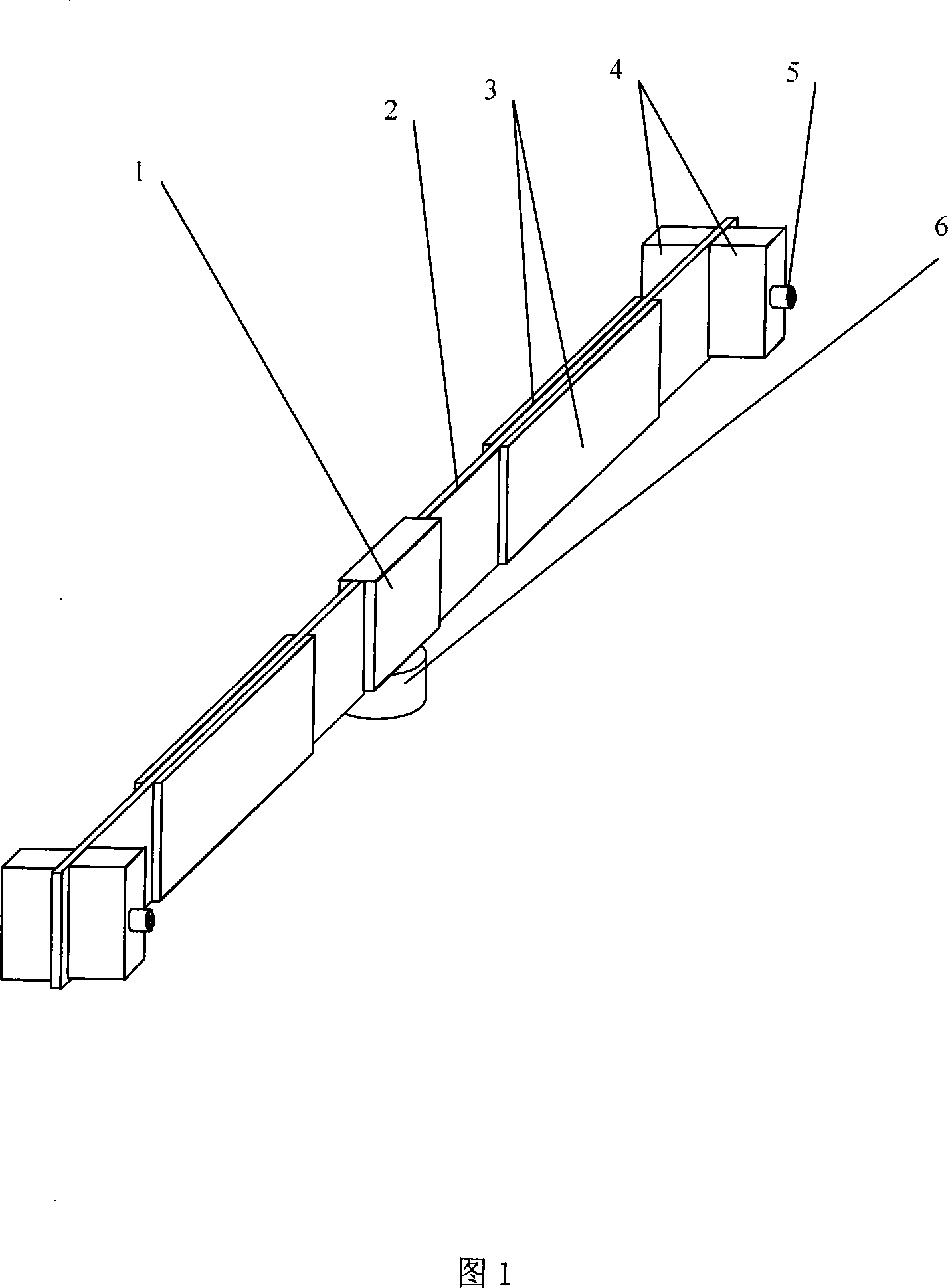
[0015] Referring to FIG. 1, the metal substrate 2 is respectively connected with four piezoelectric wafers 3 to form a piezoelectric bimorph. Both ends of the metal substrate 2 are respectively fixed to the impact mass 4 by screws 5, and the bias clamping device 1 is fixed between the metal substrate 2. The lower part of the offset clamping device is fixedly connected to the main mass 6 .

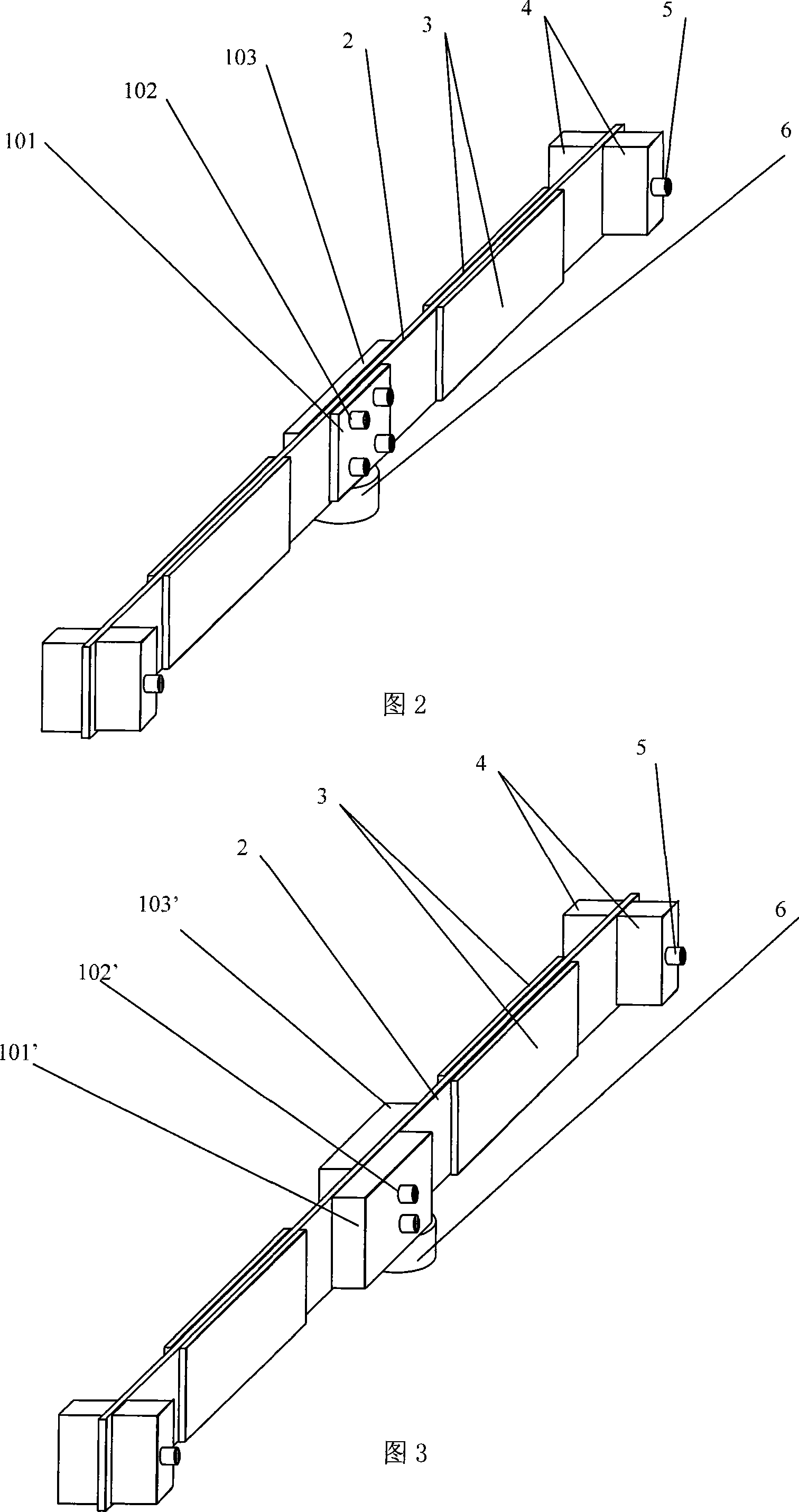
[0016] 2 is a biased support cantilever piezoelectric inertial impact linear precision driver, the piezoelectric wafer 3 is pasted on the metal substrate 2 with an adhesive, and the impact mass 4 is fixed on both ends of the metal substrate 2 with screws 5. Symmetrically arranged piezoelectric vibrators. The first pressure plate 101, the metal substrate 2 and the second pressure plate 103 are fixedly connected by screws 102, and the width of the first pressure plate 101 is smaller than that of the second pressure plate 103, thus forming the bias support of the piezoelectric vibrator. When ...

Embodiment 2

[0018] Accompanying drawing 3 is an offset support cantilever piezoelectric inertial impact rotary precision driver, which is composed of main mass 6, pressure plate three 101' and pressure plate four 103', piezoelectric wafer 3, metal substrate 2, impact mass 4 and the like. The piezoelectric wafer 3 is pasted on the metal substrate 2 with an adhesive, and the impact mass 4 is fixed on both ends of the metal substrate 2 with screws 5 to form symmetrically arranged piezoelectric vibrators. The third plate 101', the metal base plate 2 and the fourth plate 103' are fixedly connected with the screw 102', and the platen 101' and the platen 103' have the same width but are connected in dislocation, thus forming the bias support of the piezoelectric vibrator. When a symmetrical excitation electrical signal is applied, during the vibration process of the piezoelectric vibrator, two-way different impact torques will be generated due to the offset support, which realizes the one-way rot...


PUM


Abstract

A piezoelectric inertia impact precise actuator of biased support cantilever type is prepared as forming piezoelectric double-chip by connecting metal base plate separately to four piezoelectric chips, firm-jointing two ends of metal base plate with impact mass block through screws, firm-jointing bias-holding unit with middle portion of metal base plate and firm-jointing master mass block with bottom portion of bias-holding unit.

Description

technical field [0001] The invention relates to a novel piezoelectric inertial impact precision driver, belonging to the research field of micro-mechanical electronic engineering, and relates to a precision driver which adopts a piezoelectric element bias support structure to generate inertial impact force actuation. Background technique [0002] In recent years, high-precision positioning drives with piezoelectric elements as the core have been widely used in the fields of optoelectronic product assembly, micro-fabrication of precision devices, and surface atomic-level measurement. Among them, the inertial impact driver (IDM) using the dynamic characteristics of piezoelectric elements has developed into a unique driving form in the field of precision driving. Piezoelectric inertia impact driver has the characteristics of compact structure of piezoelectric mechanism, good response characteristics, no electromagnetic interference, easy control, etc. It is suitable for high-re...

Claims


Application Information

Patent Timeline
IPC IPC(8): H02N2/00H02N2/02H02N2/04
Inventor 曾平张宏壮程光明华顺明李晓韬温建明杨宝岩缪国毛艳清
Owner JILIN UNIV
Features
  • Generate Ideas
  • Intellectual Property
  • Life Sciences
  • Materials
  • Tech Scout
  • Unparalleled Data Quality
  • Higher Quality Content
  • 60% Fewer Hallucinations
Learn More