An ultrasonic imaging apparatus and a method of displaying ultrasonic images
A technology for acquiring devices and ultrasound, applied in ultrasound/sonic/infrasonic diagnosis, sonic diagnosis, infrasonic diagnosis, etc., which can solve the problem of the difficulty of knowing which direction the image moves or rotates, the difficulty of intuitively grasping the direction of the three-dimensional image, and the difficulty of intuitively grasping Issues such as the relative positional relationship between the ultrasonic probe and the 3D image
- Summary
- Abstract
- Description
- Claims
- Application Information
AI Technical Summary
Problems solved by technology
Method used
Image

Examples
Deformed example 1
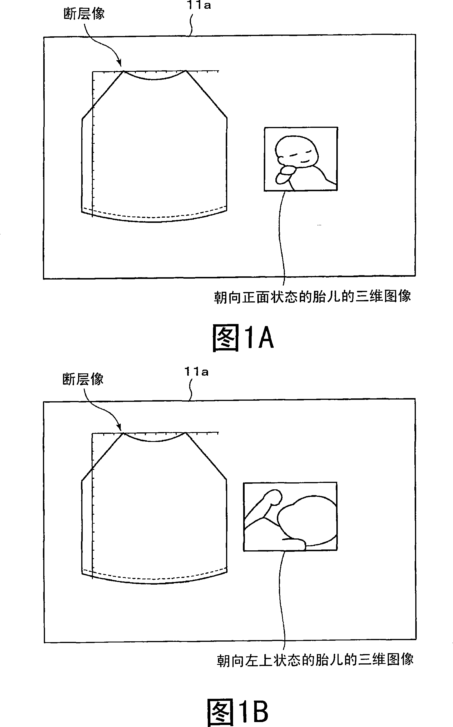
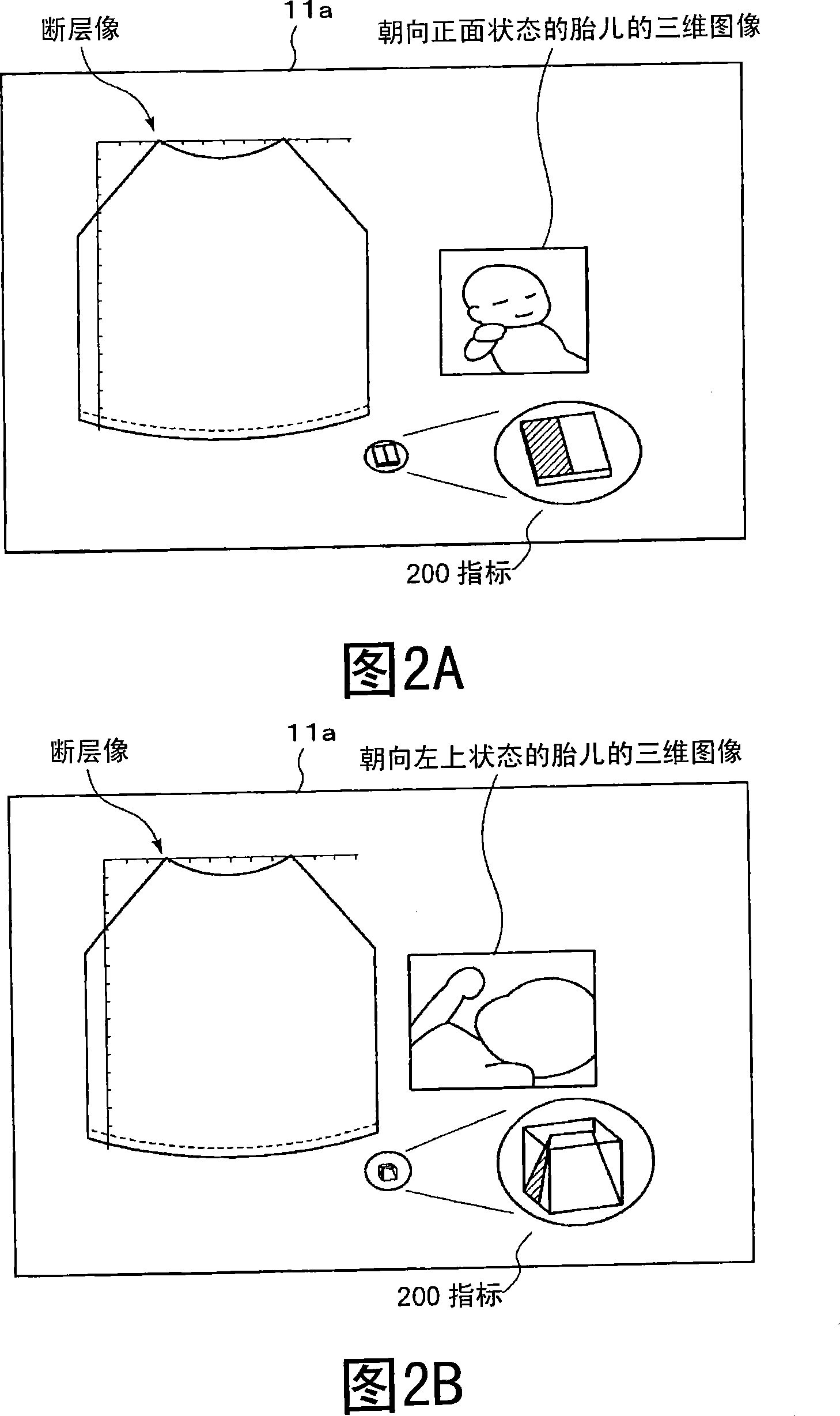
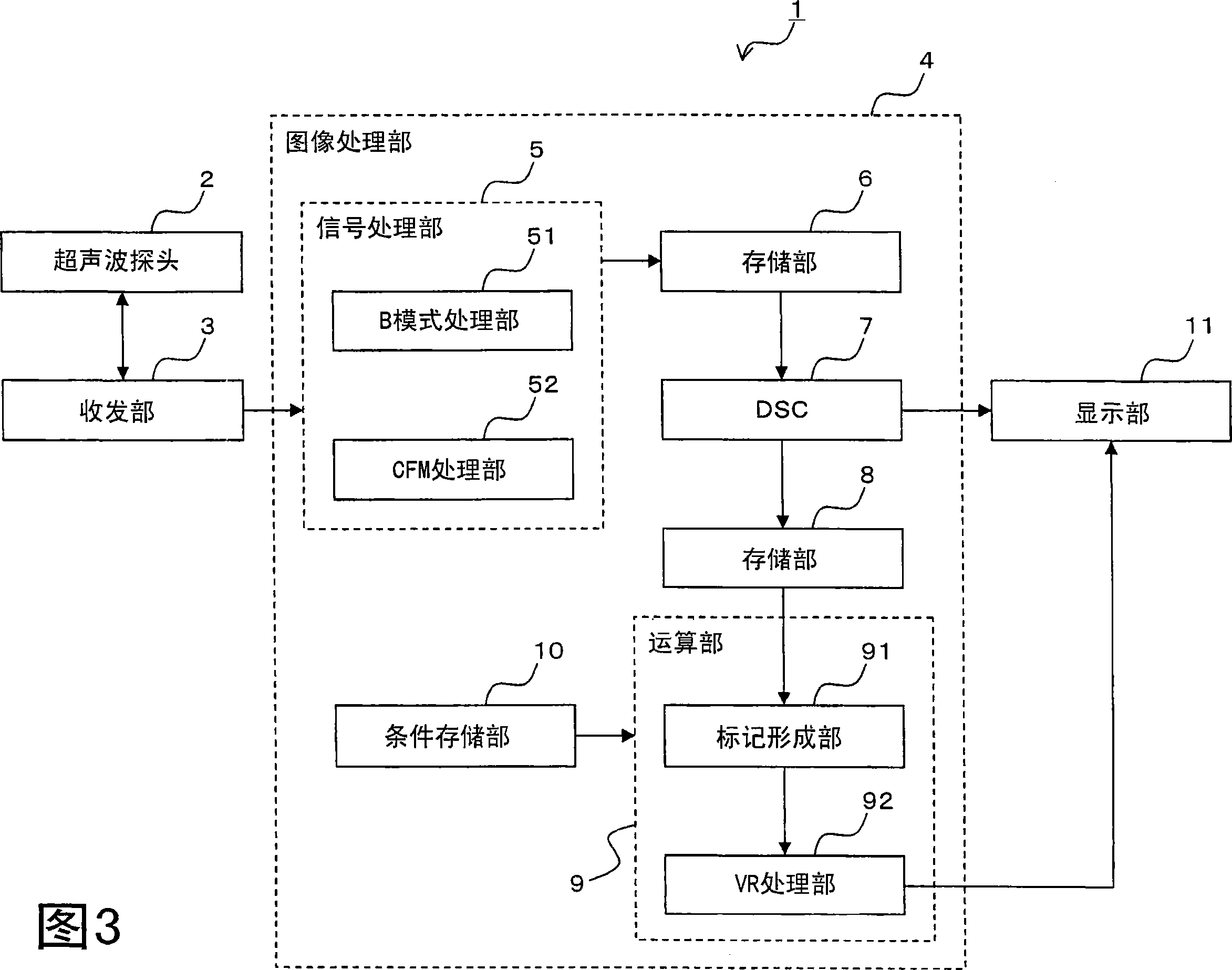
[0067]First, Modification 1 will be described with reference to FIGS. 6A and 6B . 6A and 6B are diagrams for explaining a process of superimposing and displaying a marker on a three-dimensional image, and are schematic diagrams expressing a tomographic image. For example, as shown in FIG. 6A , the mark forming unit 91 selects the tomographic image data 110 acquired at the center of the swing direction among the plurality of tomographic image data acquired along the swing direction. Then, as shown in FIG. 6B , the mark forming unit 91 writes, as a mark, a frame line 112 surrounding a preset region of interest 111 on the tomographic image data 110 acquired at the center in the swing direction. For example, the mark forming unit 91 colors the frame line 112 or sets a pixel value higher than that of the surrounding area. Information on the region of interest 111 and information on the frame line 112 are stored in the condition storage unit 10 in advance. Then, the mark forming u...
Deformed example 2
[0078] Next, Modification 2 will be described with reference to FIGS. 7A , 7B, 7C, and 7D. 7A, 7B, 7C, and 7D are diagrams for explaining the processing of superimposing and displaying a marker on a three-dimensional image, and are schematic diagrams expressing a tomographic image. As shown in FIG. 7A , the mark forming unit 91 writes marks for all tomographic image data acquired along the wobble direction. For example, as shown in FIG. 7B , the mark forming unit 91 writes a linear mark 122 transverse to the scanning direction (horizontal direction) at the center of a preset region of interest 121 for all tomographic image data 120 . This linear mark 122 is written along the scanning direction. For example, the mark forming unit 91 colors the linear mark 122 or sets the pixel value higher than that of the surrounding area. Information on the region of interest 121 and information on the linear marker 122 are stored in the condition storage unit 10 in advance. Then, the mark...
Deformed example 3
[0086] Next, modification 3 will be described with reference to FIGS. 8A , 8B, 8C, and 8D. 8A, 8B, 8C, and 8D are diagrams for explaining a process of superimposing and displaying a marker on a three-dimensional image, and are schematic diagrams expressing a tomographic image. As shown in FIG. 8A , the mark forming unit 9 writes marks for all tomographic image data acquired along the wobble direction. For example, as shown in FIG. 8B , the mark forming unit 91 writes a mark 132 at the end of a preset region of interest 131 for all the tomographic image data 130 . This mark 132 is written in the center of the region of interest 131 in the transmission and reception direction. For example, the mark forming unit 91 colors the mark 132 or sets a pixel value higher than that of the surrounding area. Information on the region of interest 131 and information on the marker 132 are stored in the condition storage unit 10 in advance. Then, the mark forming unit 91 outputs to the VR p...
PUM
 Abstract
Description
Claims
Application Information
 - R&D
- Intellectual Property
- Life Sciences
- Materials
- Tech Scout
- Unparalleled Data Quality
- Higher Quality Content
- 60% Fewer Hallucinations
Browse by: Latest US Patents, China's latest patents, Technical Efficacy Thesaurus, Application Domain, Technology Topic, Popular Technical Reports.
© 2025 PatSnap. All rights reserved.Legal|Privacy policy|Modern Slavery Act Transparency Statement|Sitemap|About US| Contact US: help@patsnap.com