Crystal-chip polishing method

A wafer and polishing machine technology, which is applied to surface polishing machine tools, grinding/polishing equipment, metal processing equipment, etc., can solve the problems of inability to adjust the pressure of the upper polishing disc, inability to realize stepless speed regulation, poor processing stability, etc. , to achieve the effect of improving polishing accuracy, small impact impact, and high processing accuracy

Inactive Publication Date: 2007-11-14
ZHEJIANG UNIV OF TECH
View PDF1 Cites 28 Cited by
  • Summary
  • Abstract
  • Description
  • Claims
  • Application Information

AI Technical Summary

Problems solved by technology

[0005] In order to overcome the shortcomings of the existing wafer polishing process that the stepless speed regulation cannot be realized, the pressure of the upper polishing disc cannot be adjusted, the processing stability is poor, and the polishing e

Method used


Image

  • Crystal-chip polishing method
  • Crystal-chip polishing method
  • Crystal-chip polishing method

Examples


Embodiment Construction

[0028] The present invention will be further described below in conjunction with the accompanying drawings.

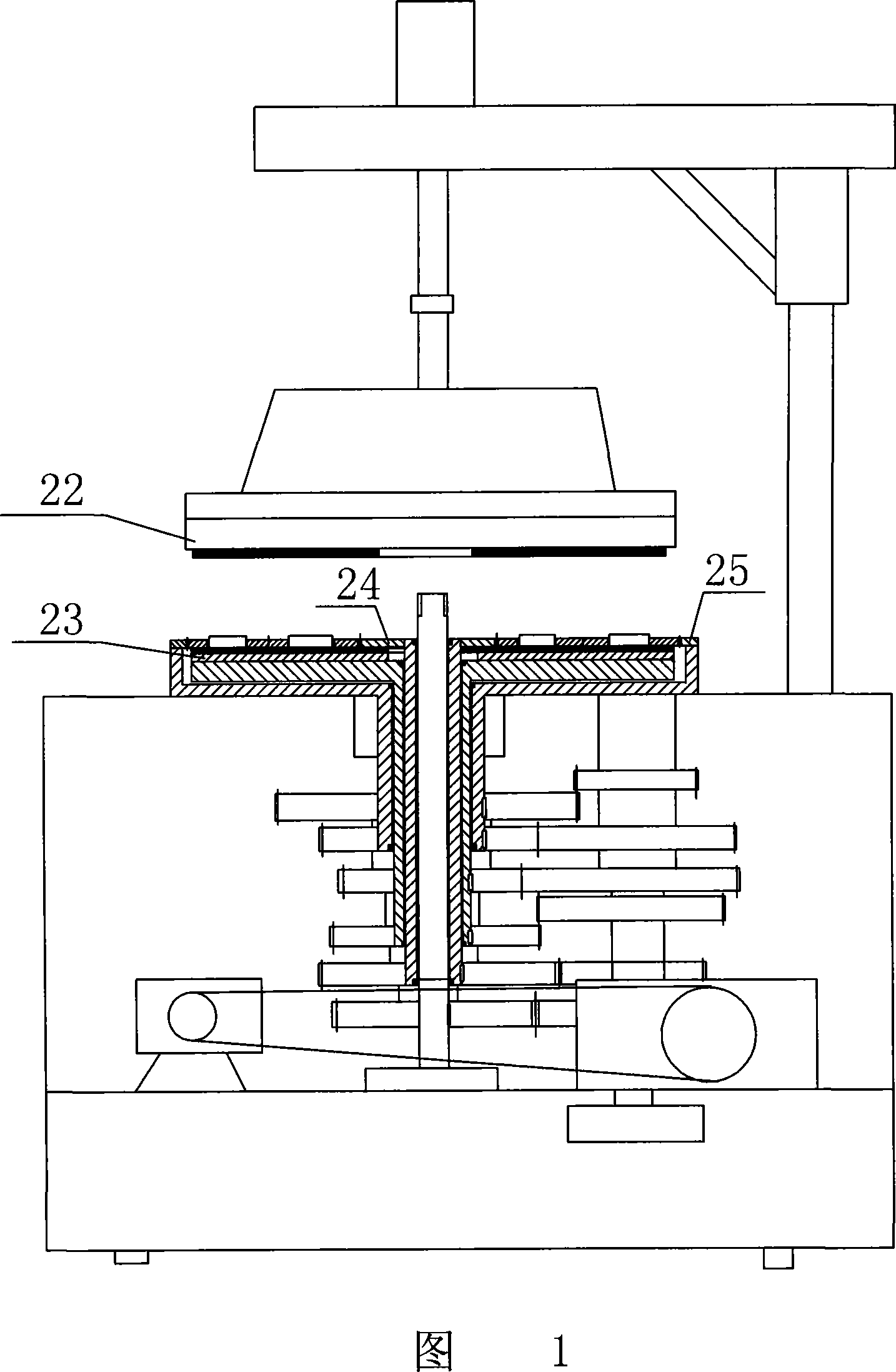
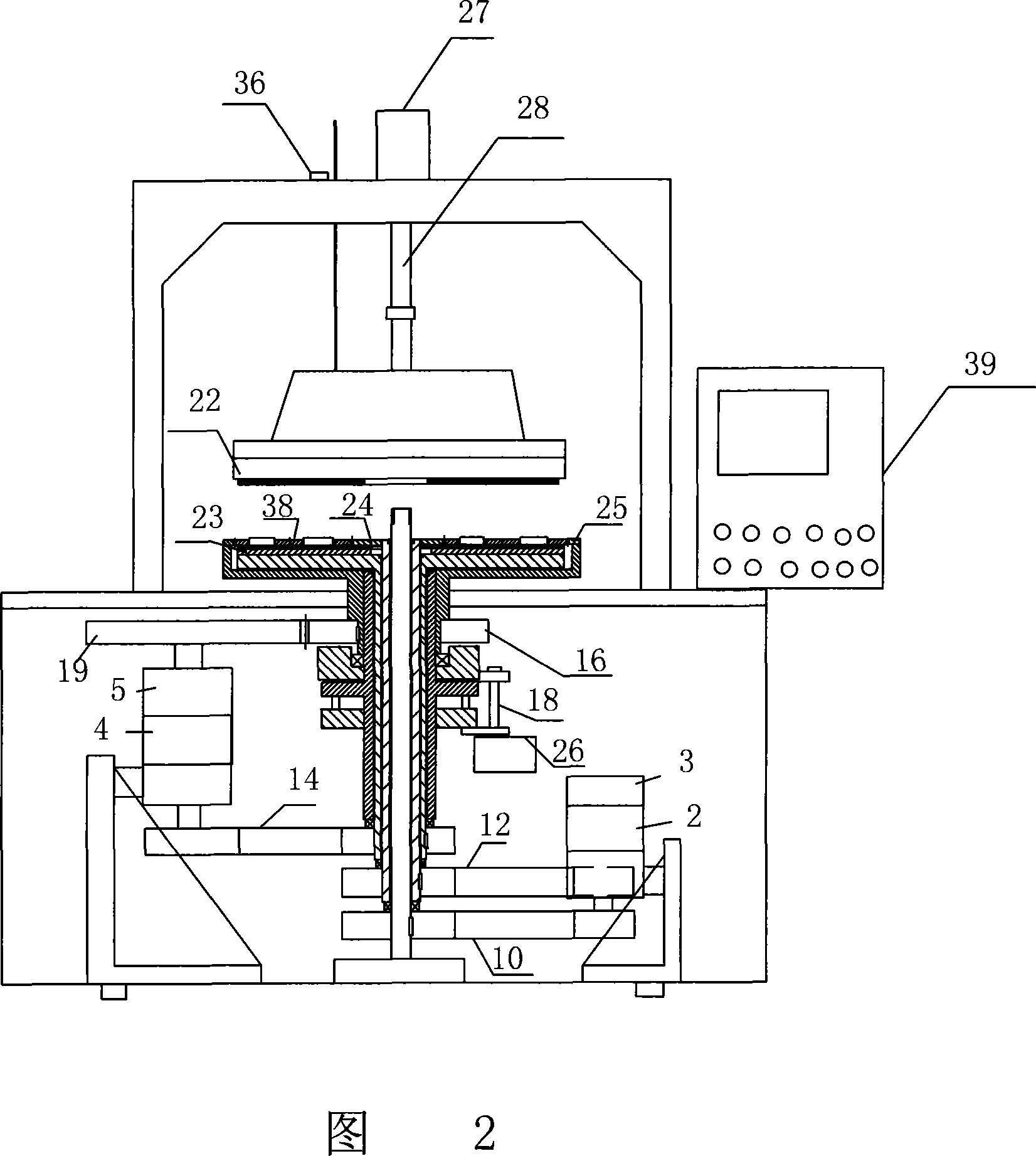
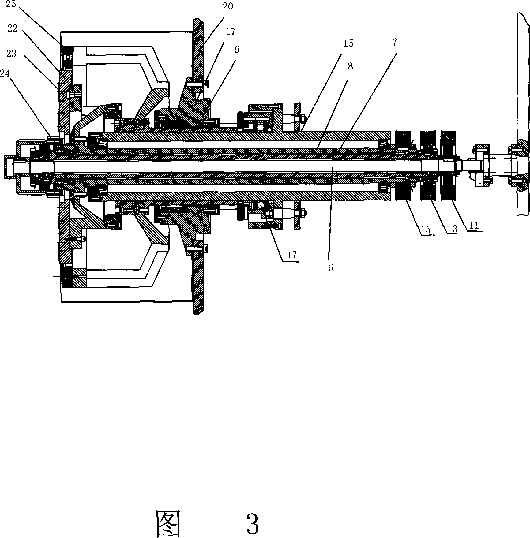
[0029] Referring to Fig. 2~Fig. 9, a kind of polishing method of wafer, this method mainly comprises the following steps:

[0030] (1) Place the wafer to be processed on the planetary wheel of the polishing machine;

[0031] (2), start the polishing machine, after the self-test of the polishing machine is normal, set the process parameters according to the wafer to be processed: the speed control curve of each variable frequency motor, the pressure control curve of the cylinder, the temperature and flow of the polishing solution;

[0032] (3) Control the lowering of the cylinder connected to the upper polishing disc and receive the signal from the position sensor. When the upper polishing disc reaches the working position, the cylinder stops and connects the upper polishing disc to the long axis;

[0033] (4) Check whether the polishing liquid delivery device is norma...


PUM


Abstract

A polishing method of wafers mainly contains the following steps: (1) put the wafers for processing on the planet gear of the polisher. (2) Startup the polisher and it can set technology parameters based on the wafers after self-checking. (3) Control the cylinder connecting with the upper polishing plate to descend and receive the signal from the position sensor. When the upper polishing plate arrive the working position, the cylinder stops and connects it with the long axis. (4) If the delivery device of polishing liquid is normal, open the polishing liquid. (5) Control the cylinder to drop continuously and test the pressure between the cylinder and the upper polishing plate by a pressure sensor. Start all conversion motors when the pressure reaches the desired value. (6) Polish the wafers by controlling the conversion motors and the cylinder based on control curves of rotating speed and pressure separately. The invention can realize infinite speed variation, adjust the pressure of the upper polishing plate, has good stationarity during processing and improves the polishing efficiency.

Description

(1) Technical field [0001] The invention relates to the field of wafer polishing, in particular to a wafer precision polishing method. (2) Background technology [0002] The original traditional polishing machine is driven by a single motor, as shown in Figure 1, through the gear transmission system to realize the rotation of the upper polishing disc 22, the lower polishing disc 23, the inner ring gear 24, and the inner gear ring 25. There are only two kinds of upper and lower polishing discs and planetary gears. The speed ratio limits the change of the trajectory of the double-sided polishing process, and lacks precise control of the speed. [0003] In order to improve the polishing efficiency, someone has improved the planetary disc of the polishing machine. For example, the Chinese utility model patent No. 02292538.4, whose patent name is the planetary disc of double-sided polishing machine, discloses a double-sided polishing disc. There are 3 eccentric holes, and 3 sepa...

Claims


Application Information

Patent Timeline
IPC IPC(8): B24B29/00
Inventor 李伟胡晓冬
Owner ZHEJIANG UNIV OF TECH
Why Eureka
Try Eureka