

Detachable mounting structure of exhaust pipe catalytic converter
Patent Information
- Authority / Receiving Office
- CN · China
- Patent Type
- Applications(China)
- Current Assignee / Owner
- LONCIN MOTOR
- Publication Date
- 2007-11-14
- Estimated Expiration
- Not applicable · inactive patent
Smart Images
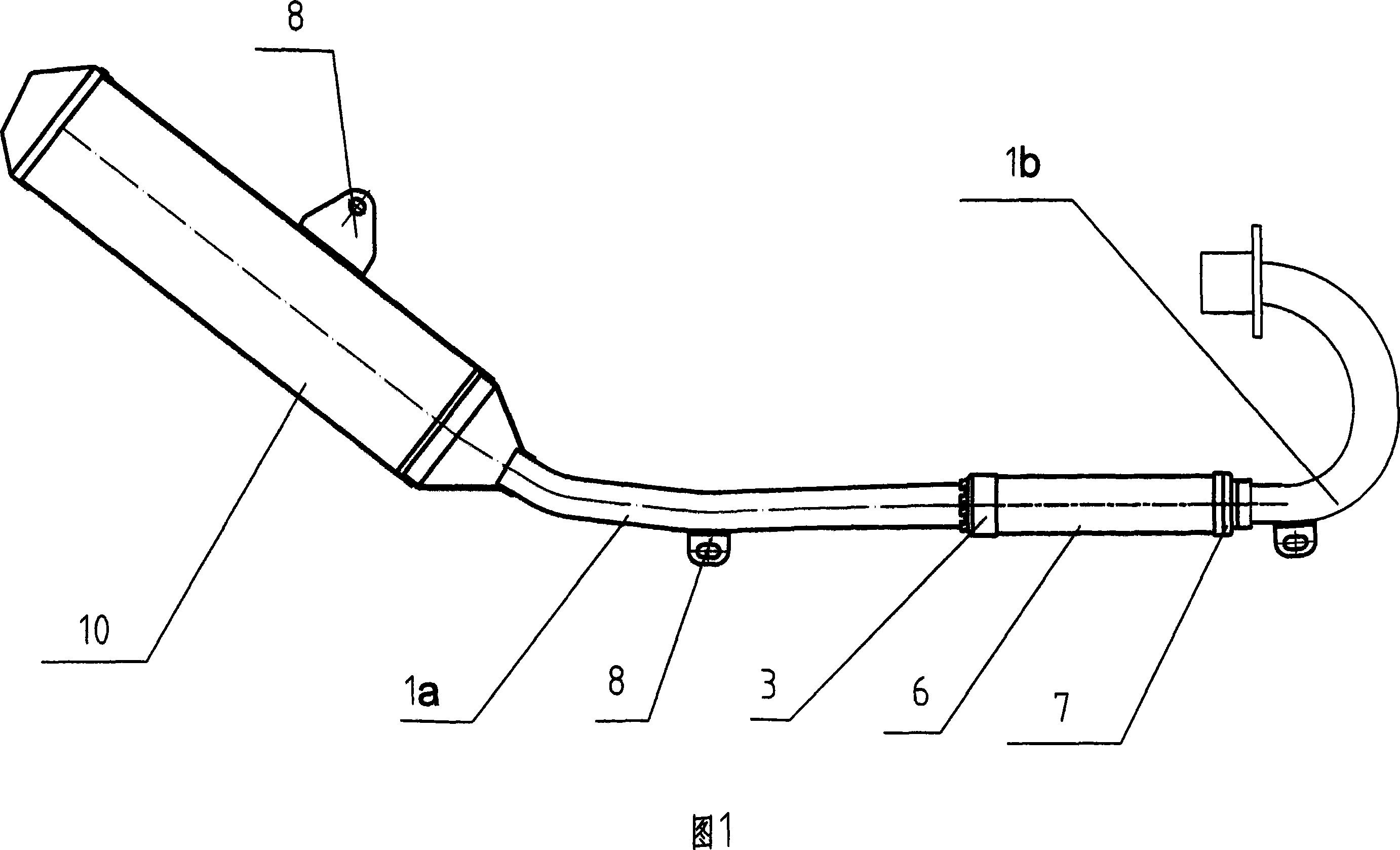
Figure 1 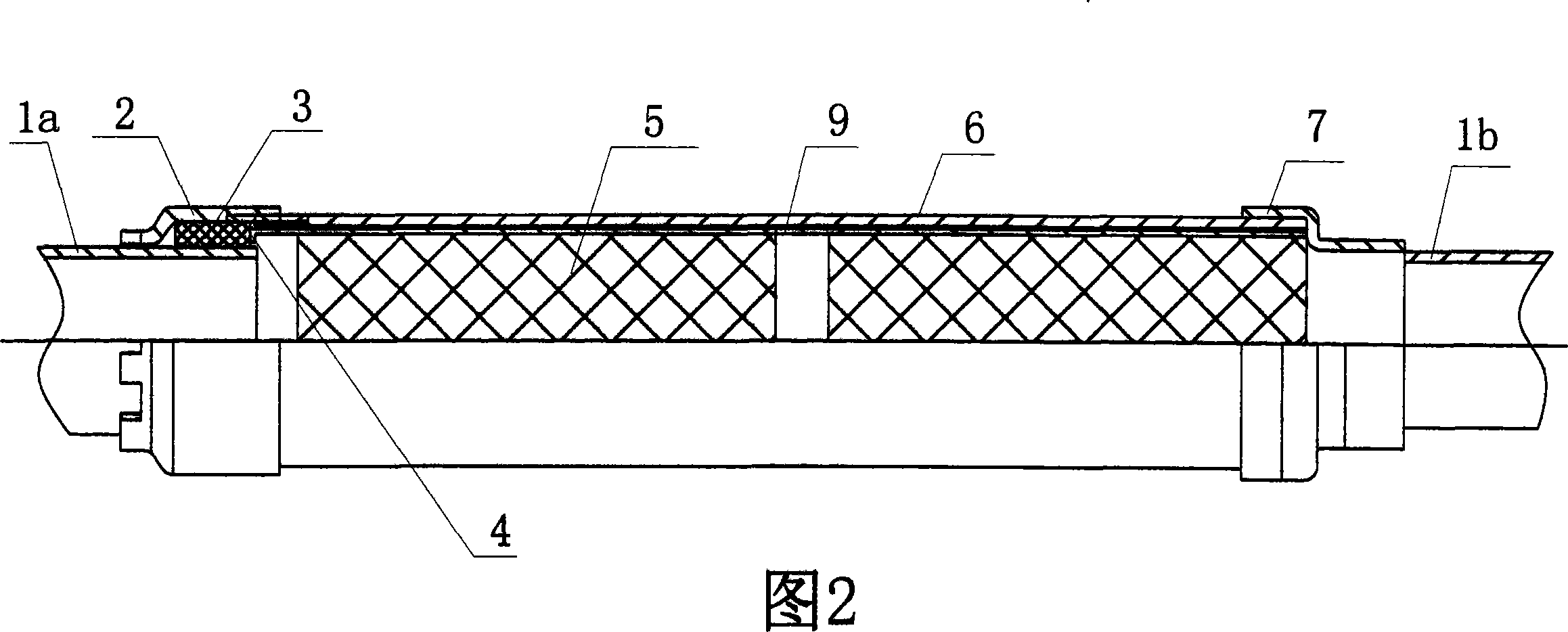
Figure 2
Abstract
Description
technical field
[0001] The invention relates to an exhaust muffler structure of a motor vehicle, in particular to a detachable installation structure of an exhaust pipe catalytic converter. Background technique
[0002] The function of the exhaust muffler of a motor vehicle is to discharge the exhaust gas of the engine into the atmosphere, reduce the noise and temperature of the exhaust gas at the same time, and eliminate the flame sparks in the exhaust gas. A good exhaust system can also improve the efficiency of intake and exhaust. Efficiency, increase engine power, reduce fuel consumption.
[0003] Motor vehicle exhaust emissions have become one of the important factors affecting the environment, so various manufacturers have taken various measures to reduce motor vehicle exhaust emissions, such as installing catalytic converters in exhaust pipes can effectively reduce motor vehicle exhaust emissions. At present, there are mainly the following ways to connect the catalyt...