
Microscope light source radiating device

A heat dissipation device and microscope technology, which is applied in the field of optical instrument components, can solve problems such as heating of the base of the microscope stand, achieve good directional heat dissipation, solve heating problems and damage work, and be easy and fast to operate

Inactive Publication Date: 2007-11-14
重庆澳浦光电技术有限公司
View PDF1 Cites 1 Cited by
  • Summary
  • Abstract
  • Description
  • Claims
  • Application Information

AI Technical Summary

Problems solved by technology

The light-collecting mirror base of the device and the directional heat dissipation fins integrated with it are made of aluminum alloy with good thermal conductivity, which can fully absorb the heat emitted by the microscope light source - the halogen bulb, and dissipate heat through the directional heat dissipation fin with a large surface area. The fins spread out, thus solving the defect of heating at the base of the microscope stand, making the operator feel comfortable, and extending the service life of the halogen bulb

Method used


Image

  • Microscope light source radiating device
  • Microscope light source radiating device

Examples


Embodiment Construction

[0018] The present invention will be further described below in conjunction with the accompanying drawings.

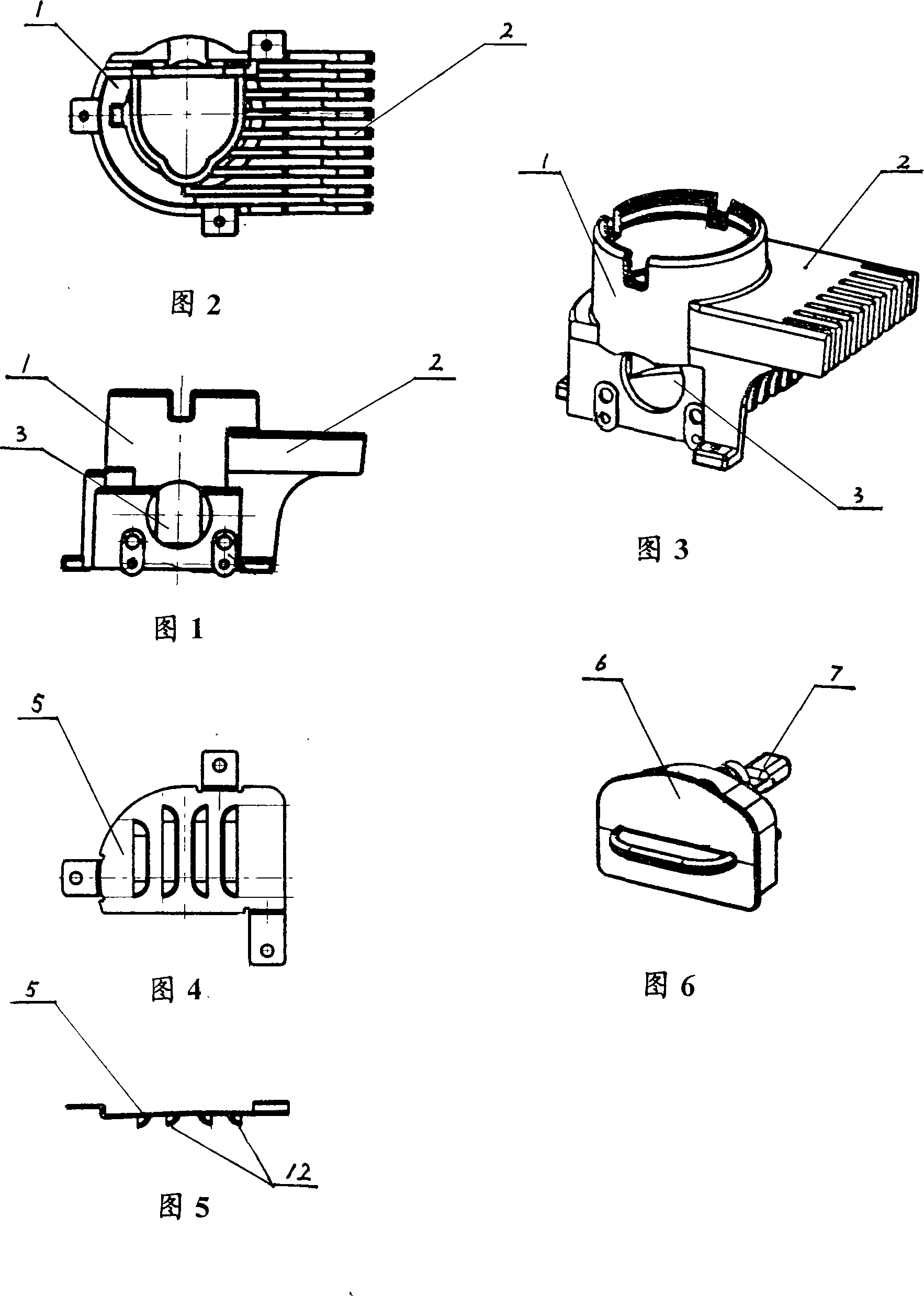
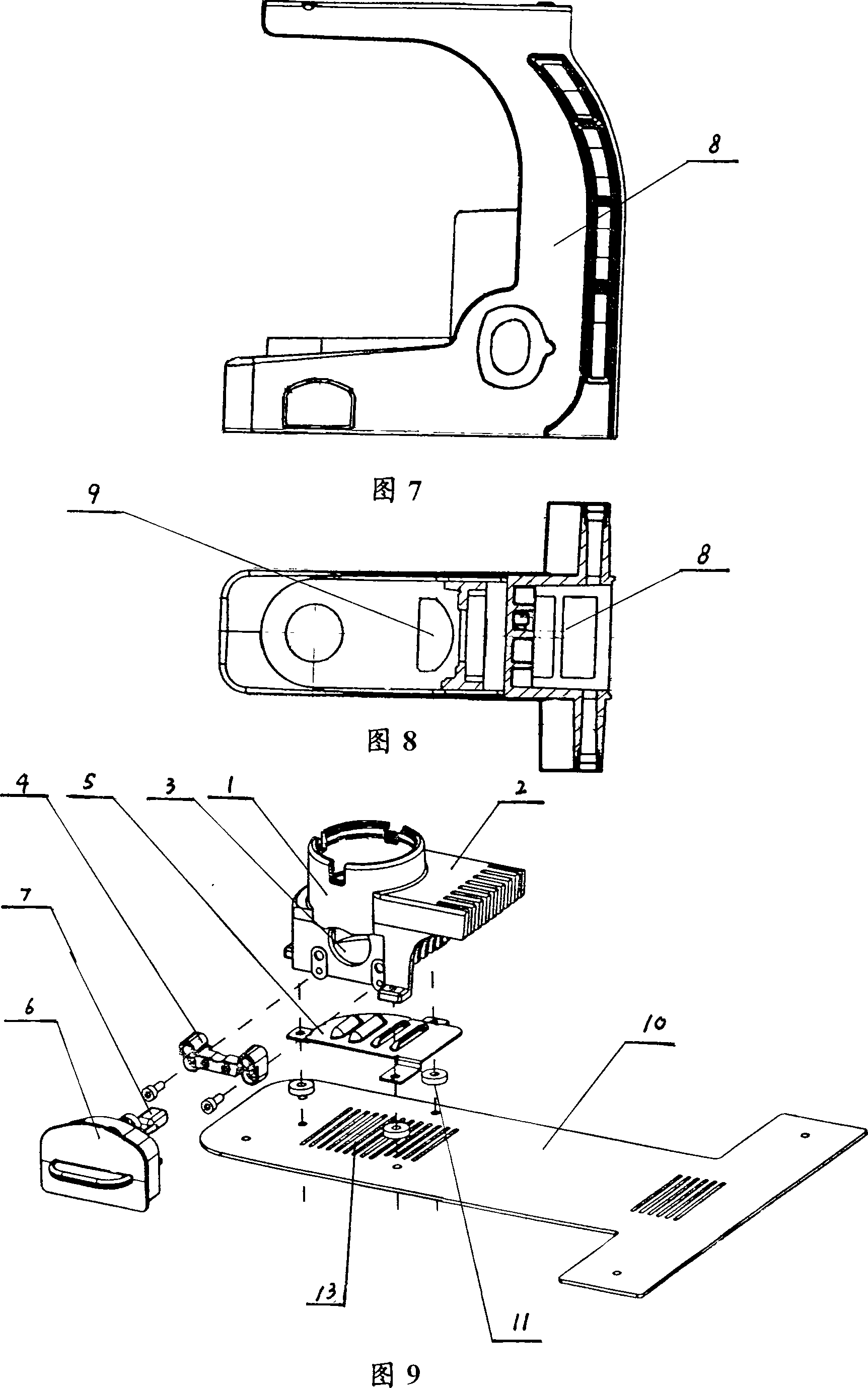
[0019] Referring to Fig. 1-Fig. 7, one side of the light-collecting mirror base 1 of the device is provided with directional cooling fins 2, and the directional cooling fins and the light-collecting mirror base are integrated; the lamp door socket 4 is positioned and connected to the The two sides of the round hole 3 of the directly lower part of the mirror base are connected to the bottom of the light-collecting mirror base with the radiating plate 5 provided with the louvers 12 opposite in the inclination direction; the halogen bulb 7 is installed on the lamp door 6, and the lamp door and the The lamp door sockets 4 on both sides of the round hole 3 at the bottom of the light collecting mirror base are mated and connected, and the halogen bulb 7 installed on the lamp door 6 is inserted into the round hole 3 at the bottom of the light collecting mirror seat.

[0020] ...


PUM


Abstract

This invention relates to light microscope cooling devices, including light-block. Characteristics:-set in the side of a mirror at its overall orientation for a cooling fin in the light microscope set at the bottom there is a hole in the bottom of the hole position on both sides of the door connecting a light socket; Set in the light microscope connected at the bottom of a heat sink. HEC also includes lamps in the door and the doors of the Halogen Lamps, lights and doors with lights door socket connections, Halogen Lamps from the light microscope set at the lower part of the hole is inserted inside. The present invention not only maintained a halogen lamps light microscope as the advantages, but also directional thermal insulation and the advantages of working long hours to resolve the microscope stent base fever and damage the issue of directional cooling effect as well, so, extend the life of the bulb; staff feel comfortable, simple and efficient operation of the replacement bulbs.

Description

technical field [0001] The invention relates to optical instrument components, in particular to a cooling device for a microscope light source. Background technique [0002] Existing microscopes generally use halogen bulbs as light sources, which have the advantages of high luminous efficiency and no reduction in luminous efficiency due to long-term use, and rich spectral curves, which can greatly improve the clarity and resolution of the microscope. But, there are following deficiencies for a long time: one is that the light source is installed in the inner cavity of the microscope support base, most of the heat that the light source sends is absorbed by the base, and a small part is discharged from the heat dissipation window located on the microscope support base; when the working time is longer, it will The base of the microscope stand is heated, and the operator cannot touch it. In severe cases, the workbench will be damaged, and the halogen bulb will be burned out. Sec...

Claims


Application Information

Patent Timeline
Patent Type & Authority Applications(China)
IPC IPC(8): G02B21/06
Inventor 陈光宇
Owner 重庆澳浦光电技术有限公司
Learn More