
Backlight module and its assemblding method

A backlight module and assembly method technology, applied in optics, nonlinear optics, instruments, etc., can solve problems such as damage to optical films

Inactive Publication Date: 2007-11-14
INNOCOM TECH SHENZHEN +1
View PDF0 Cites 26 Cited by
  • Summary
  • Abstract
  • Description
  • Claims
  • Application Information

AI Technical Summary

Problems solved by technology

[0008] In order to solve the problem that the optical film of the backlight module in the prior art is easily damaged due to mutual friction, it is necessary to provide a backlight module that can avoid damage to the optical film

Method used


Image

  • Backlight module and its assemblding method
  • Backlight module and its assemblding method
  • Backlight module and its assemblding method

Examples


Embodiment Construction

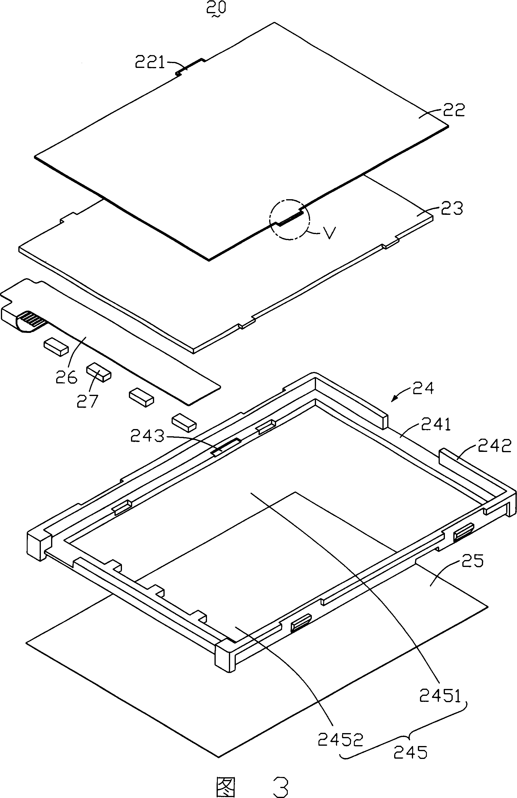
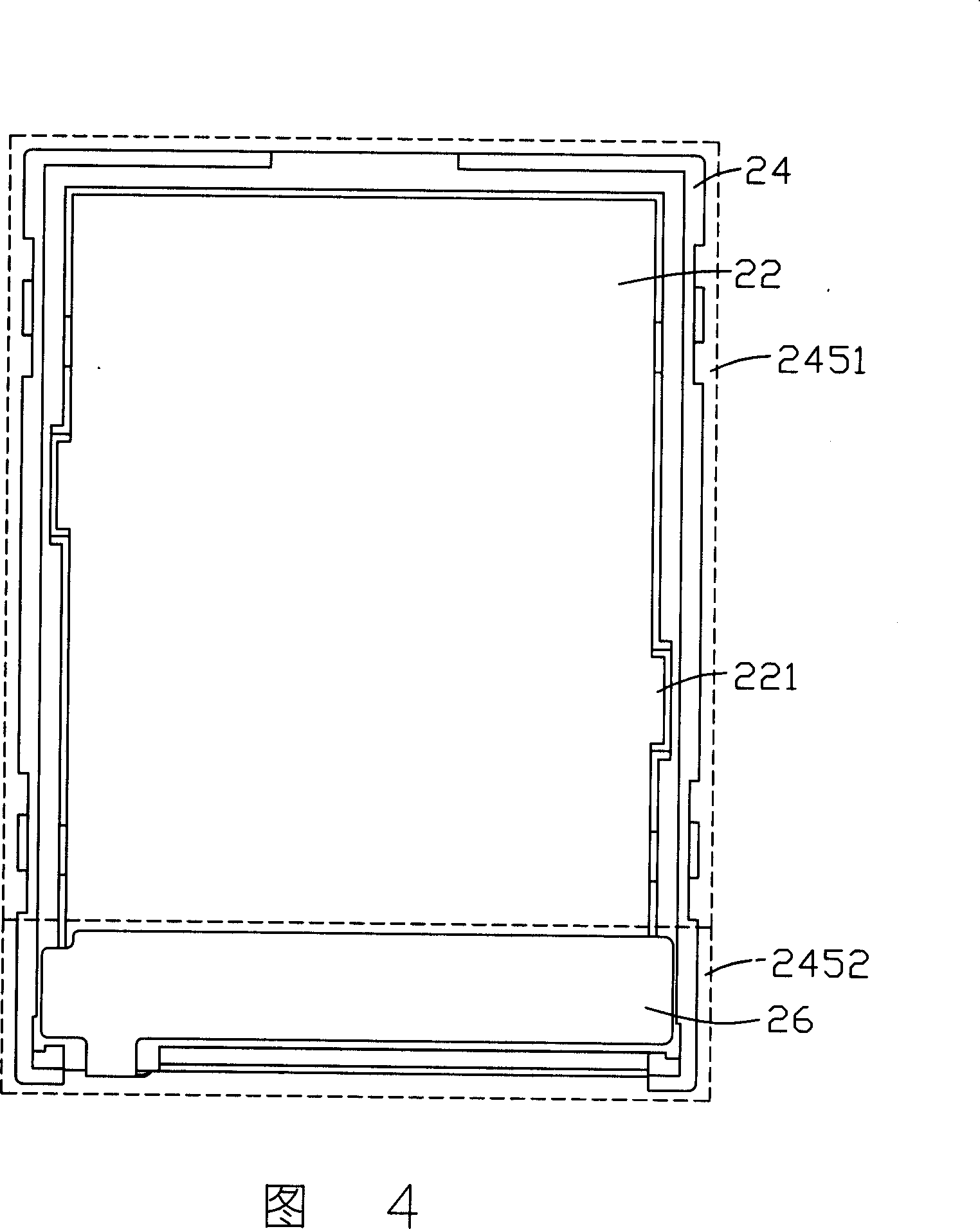
[0022] Please refer to FIG. 3 and FIG. 4 together. FIG. 3 is an exploded view of the first embodiment of the backlight module of the present invention. FIG. 4 is an assembly diagram of the backlight module shown in FIG. 3 . The backlight module 20 includes an optical film set 22 , a light guide plate 23 , a frame 24 , a reflector 25 and a flexible circuit board 26 carrying LEDs 27 . The frame 24 is a plastic frame, which is used for accommodating the optical film group 22 , the light guide plate 23 and the reflective sheet 25 which are sequentially stacked. The flexible circuit board 26 is located on one side of the light guide plate 23 and accommodated in the frame 24 .

[0023] Please refer to FIG. 5 , which is an enlarged schematic diagram of part V in FIG. 3 . The optical film set 22 is formed by laminating multiple layers of optical films, and has a protruding portion 221 and a fixing glue 223 coated on the surface of the protruding portion 221 . The protruding portion...


PUM


Abstract

The invention is a backlight module, comprising an optical diaphragm group and a frame holding the optical diaphragm group, where the optical diaphragm group, where the optical diaphragm group is stacked of multiple optical diaphragm layers and the edge of the optical diaphragm group has an integrated salient formed by salient units on the edges of these diaphragms; and the frame has a groove to hold the salient.

Description

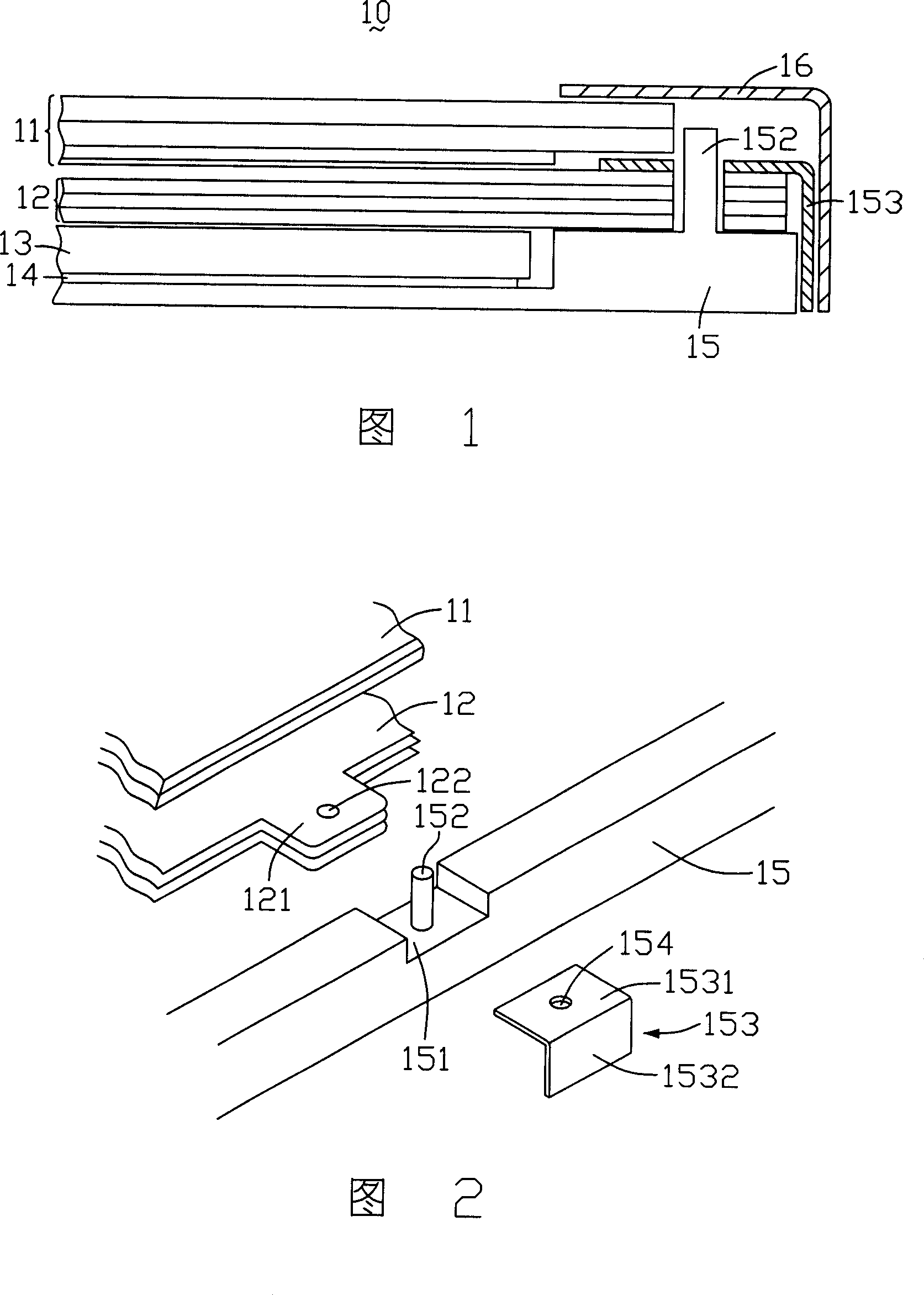
technical field [0001] The invention relates to a backlight module and an assembly method of the backlight module. Background technique [0002] Liquid crystal materials without self-luminous properties have been widely used in liquid crystal displays of different sizes used in televisions, computers, mobile phones, and personal digital assistants (Personal Digital Assistant, PDA). The backlight module provides the light source required for the display. At the same time, in order to meet the requirements of high brightness and brightness uniformity of the display, the industry usually uses optical films such as prism sheets, diffusion sheets, etc. to adjust light output. [0003] Please refer to FIG. 1 and FIG. 2 together. FIG. 1 is a partial sectional view of a prior art liquid crystal display, and FIG. 2 is a partial exploded view of the liquid crystal display shown in FIG. 1 . The liquid crystal display 10 includes a liquid crystal panel 11 , a multilayer optical film 1...

Claims


Application Information

Patent Timeline
Patent Type & Authority Applications(China)
IPC IPC(8): G02F1/13357G02F1/1333G02F1/1335
Inventor 蔡正丰余政贤
Owner INNOCOM TECH SHENZHEN
Learn More