Straight-air radiating device and its control method

A ventilation and heat dissipation and control method technology, which is applied in cooling/ventilation/heating transformation, instrument cooling, instrument and other directions, can solve the problem of increased wind resistance and achieve high efficiency

Inactive Publication Date: 2007-11-14
HUAWEI TECH CO LTD
View PDF0 Cites 40 Cited by
  • Summary
  • Abstract
  • Description
  • Claims
  • Application Information

AI Technical Summary

Problems solved by technology

[0019] The embodiment of the present invention provides a direct ventilation cooling device and its control method, which can so

Method used


Image

  • Straight-air radiating device and its control method
  • Straight-air radiating device and its control method
  • Straight-air radiating device and its control method

Examples


Embodiment Construction

[0039] The present invention will be described in detail below with reference to the accompanying drawings and in combination with embodiments.

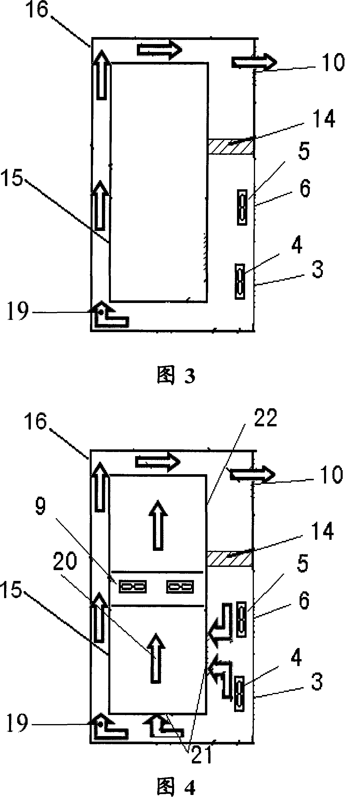
[0040] Figure 3 shows a structural diagram of a straight ventilation cooling device according to an embodiment of the present invention, including: a cabinet 16; an equipment subframe 15 arranged in the central area of ​​the cabinet 16; a first air inlet 3 or 6 and a first air outlet 10 , are located on the first side of the cabinet 16; the windshield 14, which is arranged in the gap between the first side of the cabinet 16 and the equipment subframe 15, cuts off the first air inlet 3, 6 and the first air outlet 10 in this Communication at the gap; the first air duct 19 , which connects the first air inlets 3 , 6 and the first air outlet 10 , is formed by the gap between the other three sides of the cabinet 16 and the equipment subframe 15 .

[0041] This embodiment optimizes the design of the air duct, and uses the upper and lower a...


PUM


Abstract

The heat sink includes following parts: cabinet; insertion frame for equipment setup at central area of the cabinet; both of first air inlet and first air outlet positioned at first side of the cabinet; being setup at gap between first side of the cabinet and insertion frame for equipment, the shield plate is in use for obstructing connection at the gap between first air inlet and first air outlet; being connecting first air inlet and first air outlet, first air channel is formed from gaps between other three side surfaces of the cabinet and insertion frame for equipment. The invention also discloses method for controlling the heat sink in type of conduction through. Features are: reasonable overall arrangement for air channel, and no reversed-flow region.

Description

technical field [0001] The invention relates to the technical field of electronic communication, in particular to a direct ventilation heat dissipation device and a control method thereof. Background technique [0002] With the diversification of market demand, in various industries such as chemical industry, HVAC, machinery, and communication, the functional requirements for outdoor equipment are getting higher and higher, which leads to an increase in the configuration power of the equipment. However, most of the electrical energy consumed by the equipment during operation will be converted into heat energy, and overheating of the equipment will lead to a decrease in the performance of the equipment and even cause damage. In order to ensure the normal operation of the equipment, the temperature of the equipment must be within the allowable range, and it is urgent to solve the heat dissipation problem in the equipment. Product miniaturization is the trend of today's market...

Claims


Application Information

Patent Timeline
IPC IPC(8): H05K7/20G12B15/04
CPCH05K7/20618H05K7/207
Inventor 万玉喜彭锋胡卫峰彦斯
Owner HUAWEI TECH CO LTD
Why Eureka
Try Eureka