Relay connection member, inspection device and method of manufacturing relay connection member

A technology for connecting components and manufacturing methods, which is applied in the direction of connection, conductive connection, measuring device, etc., and can solve the problem of disconnection of the wiring structure 106, poor electrical connection between the relay connection member 104 and the inspection circuit 105, and the failure to rule out the relay connection member 104 and the probe 102 are electrically connected to achieve good electrical conduction, ensure electrical conduction, and suppress positional deviation

Inactive Publication Date: 2010-05-26
NHK SPRING CO LTD
View PDF5 Cites 1 Cited by
  • Summary
  • Abstract
  • Description
  • Claims
  • Application Information

AI Technical Summary

Problems solved by technology

[0005] However, conventional inspection devices have the problem that the possibility of poor electrical connection between the relay connection member 104 and the probe 102 and the electrical connection between the relay connection member 104 and the inspection circuit 105 cannot be ruled out.
Since such a connection form is a physically far-fetched structure, new problems such as disconnection in a part of the wiring structure 106 with low physical strength will occur.

Method used


Image

  • Relay connection member, inspection device and method of manufacturing relay connection member
  • Relay connection member, inspection device and method of manufacturing relay connection member
  • Relay connection member, inspection device and method of manufacturing relay connection member

Examples


Embodiment Construction

[0026] Hereinafter, the best mode (hereinafter referred to as "embodiment") for implementing the inspection device and the relay connection member constituting the inspection device of the present invention will be described in detail with reference to the drawings. However, it should be noted that the drawings are schematic diagrams, and the relationship between the thickness and width of each part, the ratio of the thickness of each part, etc. may be different from the actual ones. Of course, the drawings also include parts with different dimensional relationships or ratios. .

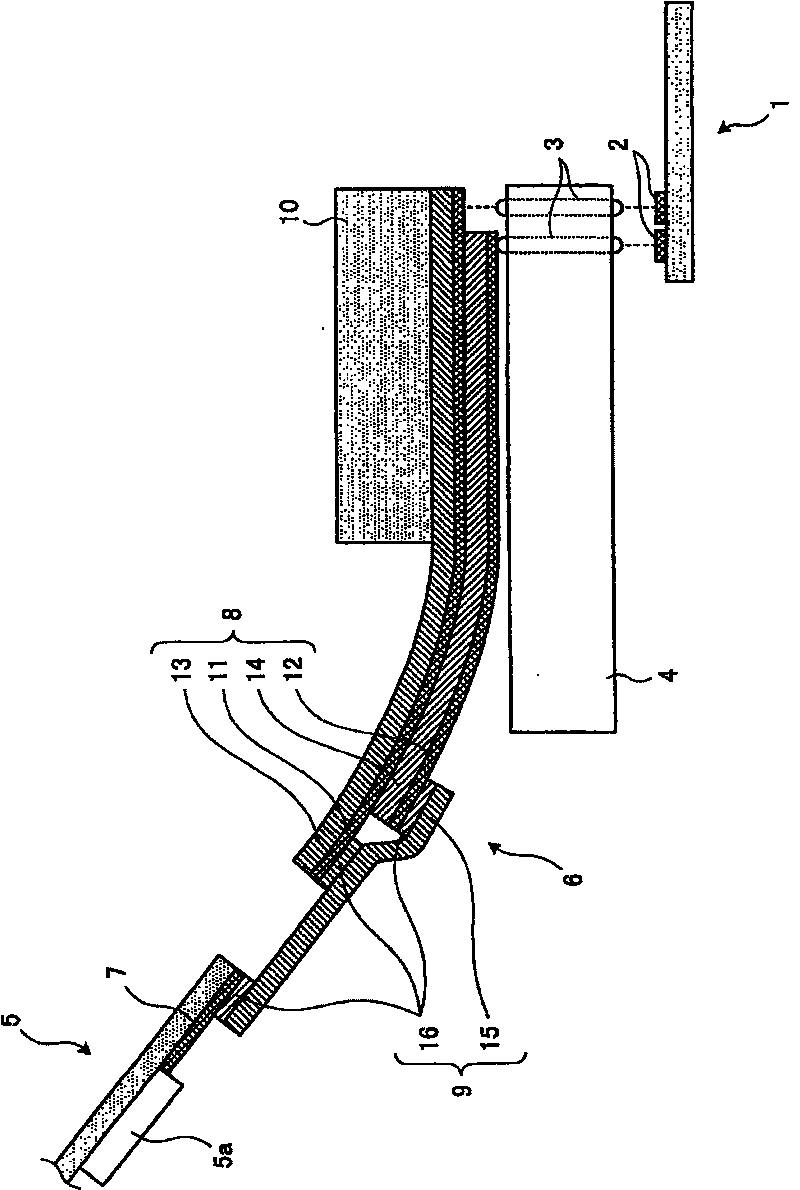
[0027] figure 1 It is a schematic diagram showing the overall configuration of the inspection device according to the embodiment. Such as figure 1 As shown, the inspection device of this embodiment includes: a probe 3 whose end is in contact with a terminal 2 of an inspection object 1; a probe holder 4 that holds the probe 3 at a predetermined position; An inspection circuit 5 outputting at leas...


PUM


Abstract

There is provided an inspection device capable of assuring electrical connection to an inspection object and internal electrical connection while coping with downsizing of a terminal of the inspectionobject. The inspection device includes probe (3), a probe holder (4) holding the probe (3), an inspection circuit (5) for outputting an inspection signal to an inspection object (1) via the probe (3), and a relay connection member (6) for electrically connecting the probe (3) to the inspection circuit (5). The relay connection member (6) includes a first connection member (8) having first wiringstructures (11, 12) electrically connected to the probe (3), adjacent structures being formed on different layers, and a second connection member (8) having a second wiring structure (16) electricallyconnected to the wiring structure (7) arranged on the inspection circuit and formed on the same layer. The relay connection member (6) includes the first connection member (8) appropriate for connection to the probe (3) and the second connection member (9) appropriate for connection to the inspection circuit (5). Thus, it is possible to realize preferable electrical connection to both of them.

Description

technical field [0001] The present invention relates to an inspection method for outputting an inspection signal used for the inspection with the other ends of a plurality of probes whose ends are in contact with a plurality of terminals formed on the inspection object when inspecting a designated inspection object. A relay connecting member for electrically connecting circuits, an inspection device using the relay connecting member, and a method for manufacturing the relay connecting member. Background technique [0002] Conventionally, an inspection device for inspecting electrical characteristics of electronic components such as liquid crystal panels is known. As such inspection devices, such as Figure 5 As shown, it is formed by the following parts, namely: a plurality of probes 102 provided corresponding to terminals 101a of an inspection object 101 as an electronic component; a probe holder for holding a plurality of probes 103 ; an inspection circuit 105 for outputt...

Claims


Application Information

Patent Timeline
Patent Type & Authority Patents(China)
IPC IPC(8): G01R1/06G01R31/28H01R11/01
CPCG01R31/2889G01R1/06
Inventor 外间裕康风间俊男
Owner NHK SPRING CO LTD
Why Eureka
Try Eureka