Medium-spanning steel-pipe concrete truss bridge
A technology of steel tube concrete and truss girders, which is applied to truss bridges, bridges, bridge parts, etc., can solve the problems of large number of pile foundations, high bridge construction cost, and large amount of steel bars, so as to reduce bridge construction costs, accelerate development, and increase construction speed Effect
- Summary
- Abstract
- Description
- Claims
- Application Information
AI Technical Summary
Problems solved by technology
Method used
Image

Examples
Embodiment Construction
[0013] The present invention will be further described below in conjunction with the accompanying drawings and embodiments.
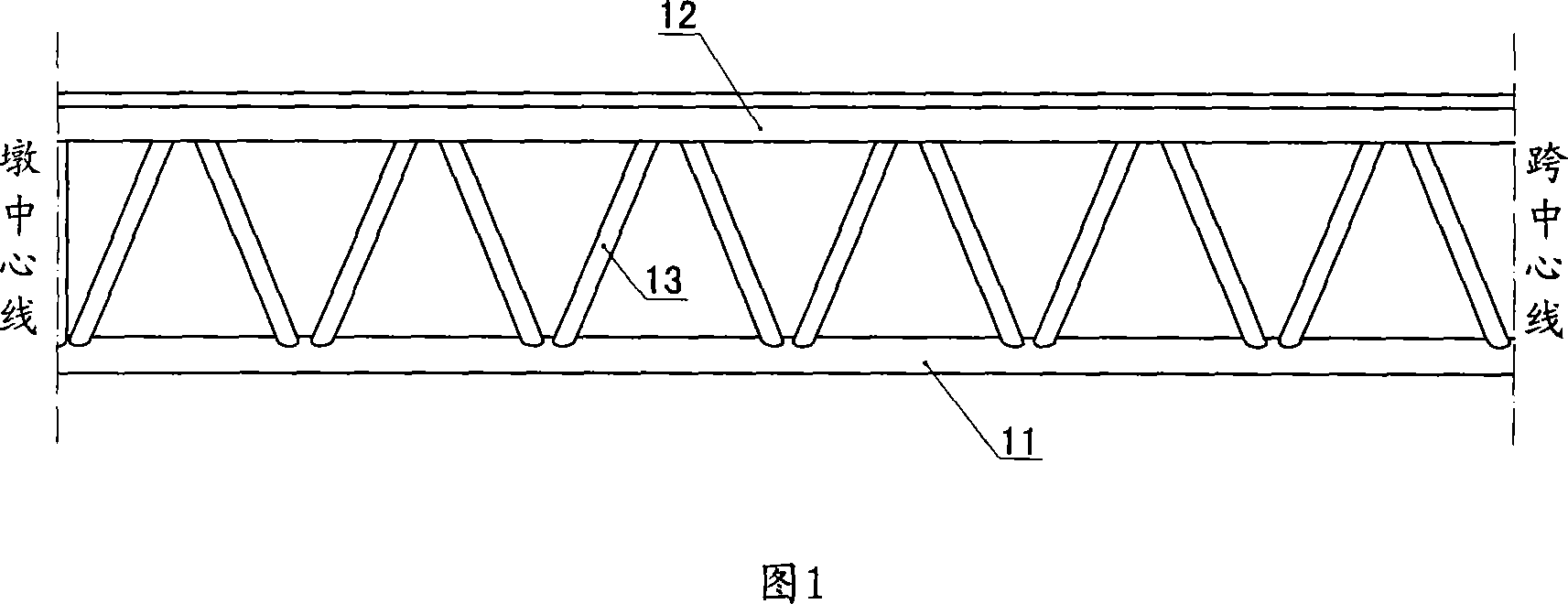
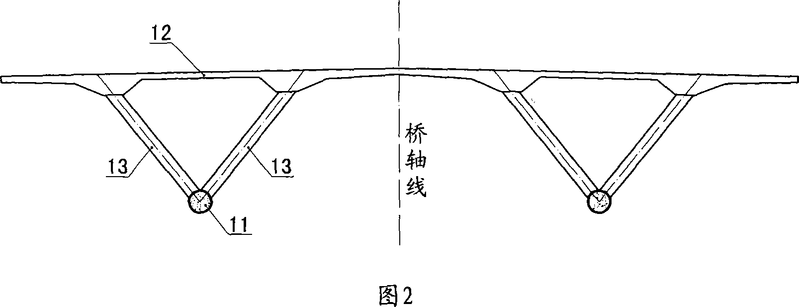
[0014] Referring to Fig. 1, the medium-span concrete-filled steel tube truss girder bridge of the present invention includes a main girder erected on the top of the pier, and the main girder is composed of a lower chord 11, an upper chord skeleton 12, and several web tubes 13 arranged at intervals and having vertical and horizontal inclinations. constitute. Referring to Figure 2, the upper and lower ends of each web tube 13 are fixedly connected to the lower chord 11 and the upper chord skeleton 12 respectively to form a truss beam whose cross section is triangular.
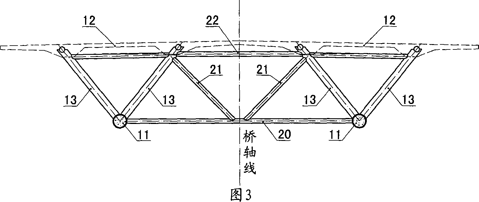
[0015] Referring to Figure 2, the main girder is usually designed with a frame structure, that is, left and right truss girders are arranged in its transverse direction, and the left and right truss girders are connected as a whole through connecting members. As a typical configuration, w...
PUM
 Abstract
Description
Claims
Application Information
 - R&D
- Intellectual Property
- Life Sciences
- Materials
- Tech Scout
- Unparalleled Data Quality
- Higher Quality Content
- 60% Fewer Hallucinations
Browse by: Latest US Patents, China's latest patents, Technical Efficacy Thesaurus, Application Domain, Technology Topic, Popular Technical Reports.
© 2025 PatSnap. All rights reserved.Legal|Privacy policy|Modern Slavery Act Transparency Statement|Sitemap|About US| Contact US: help@patsnap.com