Display device, display panel driver and method of driving a display panel
A display device and display panel technology, applied to static indicators, instruments, optics, etc., can solve the problems of increased power consumption and achieve the effect of reducing power consumption
- Summary
- Abstract
- Description
- Claims
- Application Information
AI Technical Summary
Problems solved by technology
Method used
Image
Examples
no. 1 example
[0035] (The overall structure)
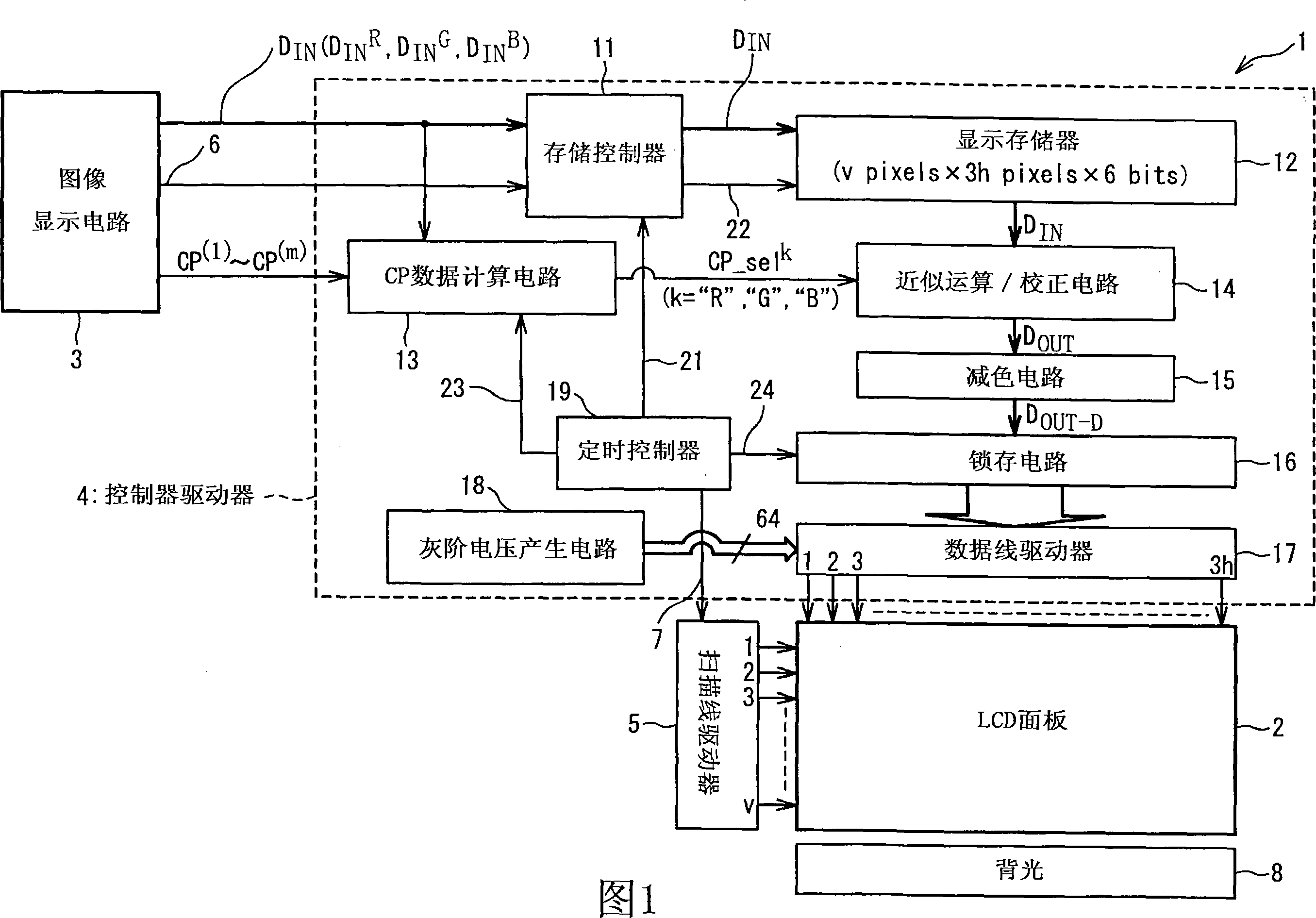
[0036] FIG. 1 is a block diagram showing the configuration of a system including a liquid crystal display (LCD) device 1 according to an embodiment of the present invention. The LCD device 1 is provided with an LCD panel 2 , a controller driver 4 , a scan line driver 5 and a backlight 8 for illuminating the LCD panel 2 . The LCD device 1 is configured to display images on the LCD panel 2 in response to various data and control signals sent from the image display circuit 3 .
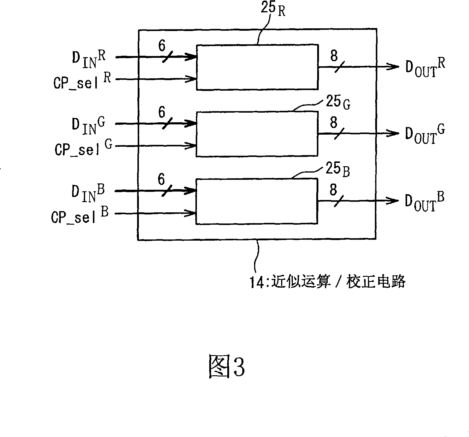
[0037] The image display circuit 3 generates input grayscale data D corresponding to an image to be displayed on the LCD panel 2 IN , and provide it to the controller driver 4. In this embodiment, the input gray scale data D IN It is 6-bit data. The input gray scale data D associated with the red pixel (R pixel) of the LCD panel 2 will be IN Called the input grayscale data D IN R . Similarly, the input grayscale data D associated with green pixels (G pixels) and bl...
no. 3 example
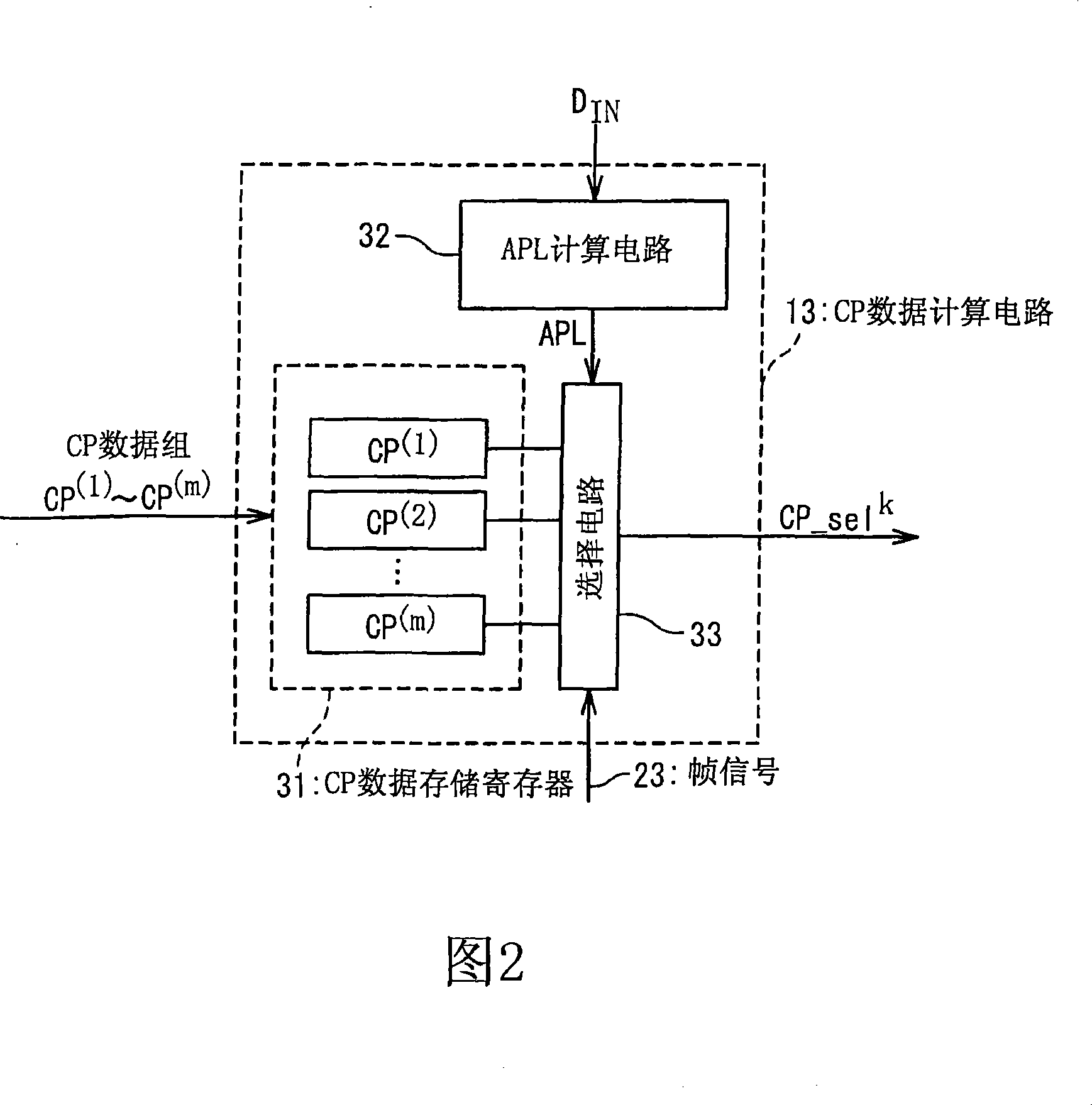
[0146] In the third embodiment, the selected correction point data set CP_sel R , CP_sel G and CP_sel B It is selected according to the frequency distribution of the input grayscale data of each frame image, not according to the APL of the frame image; and thus realizes the conversion of the gamma value γ used in the gamma correction. In other words, the frequency distribution of the input gray scale data is used as an indication of the brightness of each frame image, and the gamma value γ used in the gamma correction is converted according to the brightness of each frame image. For the purpose of converting the gamma value γ according to the frequency distribution of the input grayscale data, the correction point data calculation circuit 13B shown in FIG. 9 is used instead of the correction point data calculation circuit shown in FIG. 2 in the third embodiment. 13.
[0147] The correction point data calculation circuit 13B is provided with a correction point data storage r...
no. 4 example
[0155] According to the fourth embodiment, not only the gamma value γ is converted according to the frequency distribution of the input grayscale data, but also the correction point data CP0 to CP5 are corrected according to the frequency distribution of the input grayscale data, and thus it is possible to better control The contrast of the image. As described above, the correction point data CP0 to CP5 are basically determined by equation (1a) or (1b). In the fourth embodiment, the correction point data CP1 and CP4 among the correction point data CP0 to CP5 determined by the equation (1a) or (1b) are corrected according to the frequency distribution of the input grayscale data, and thus The contrast of the image can be controlled more appropriately. For the purpose of converting the gamma value γ according to the frequency distribution of the input grayscale data and further correcting the correction point data CP1 and CP4, a correction point data calculation circuit 13C sho...
PUM
 Abstract
Description
Claims
Application Information
 - R&D
- Intellectual Property
- Life Sciences
- Materials
- Tech Scout
- Unparalleled Data Quality
- Higher Quality Content
- 60% Fewer Hallucinations
Browse by: Latest US Patents, China's latest patents, Technical Efficacy Thesaurus, Application Domain, Technology Topic, Popular Technical Reports.
© 2025 PatSnap. All rights reserved.Legal|Privacy policy|Modern Slavery Act Transparency Statement|Sitemap|About US| Contact US: help@patsnap.com


