

Power supply circuit device and electronic apparatus provided therewith
A technology of power supply circuit and current detection circuit, applied in emergency protection circuit devices, output power conversion devices, circuits, etc., can solve the problems of high electric power and affect the service life of batteries, etc., to achieve stable brightness, prolong service life, reduce The effect of electrical power consumption
- Summary
- Abstract
- Description
- Claims
- Application Information
AI Technical Summary
Problems solved by technology
Method used
Image

Examples
no. 1 example
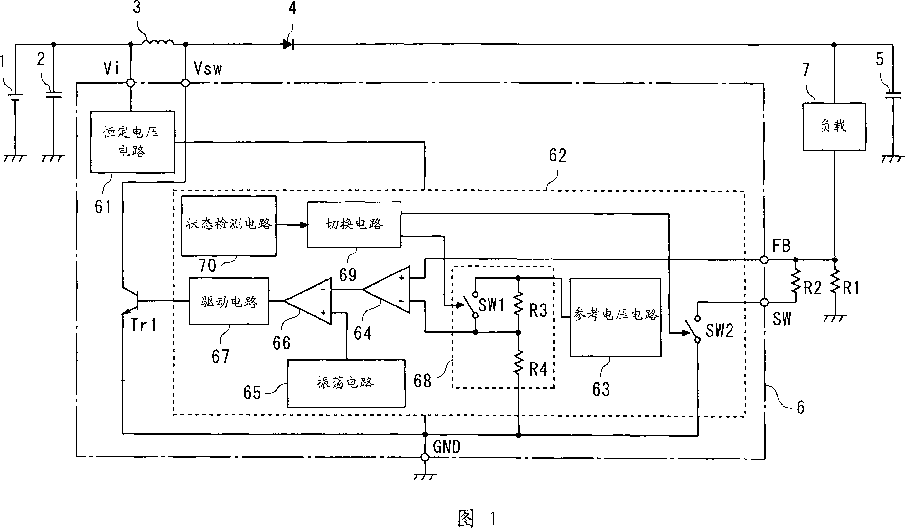
[0035] A first embodiment of the present invention will be described with reference to the drawings. FIG. 1 is a block diagram showing the internal configuration of the power supply circuit device of the present embodiment. In FIG. 1 , circuit blocks that are used for the same purpose as those in the conventional power supply circuit device shown in FIG. 12 are denoted by the same reference numerals, and their detailed description will not be repeated.
[0036] As in the case of the power circuit device shown in FIG. 12, the power circuit device shown in FIG. 1 includes a DC (direct current) power source 1, an input capacitor 2, a coil 3, a diode 4, an output capacitor 5, and a resistor R1 , and provide the boosted output voltage to the load 7. The power circuit arrangement shown in FIG. 1 also comprises a control circuit arrangement 6 for switching between storing energy into the coil 3 and releasing energy from the coil 3 . Similar to the control circuit device 60 of the p...
no. 2 example
[0061] A second embodiment of the present invention will be described with reference to the drawings. As in the case of the power supply circuit device of the first embodiment, the power supply circuit device of the present embodiment is configured as shown in the block diagram of FIG. 1 . In the following description, only the differences from the power supply circuit device of the first embodiment are explained, and explanations for those circuit blocks that can also be found in the first embodiment will no longer be as in the first embodiment Repeat as in.
[0062] Unlike the power supply circuit device of the first embodiment, the power supply circuit device of the present embodiment makes the output current to the load 7 smaller than that in normal operation when low-power operation is performed. That is, it is assumed that the output current flowing through the load 7 in normal operation is Io, and the output current flowing through the load 7 in low power operation is ...
no. 3 example
[0068] A third embodiment of the present invention will be described with reference to the drawings. FIG. 4 is a block diagram showing the internal configuration of the power supply circuit device of the present embodiment. In FIG. 4 , those circuit blocks that are used for the same purpose as in the power supply circuit device shown in FIG. 1 are identified with the same reference numerals, and their detailed description will not be repeated.
[0069] Unlike the power circuit device of the first embodiment (see FIG. 1 ), the power circuit device of this embodiment has a configuration in which switching between normal operation and low power operation is performed based on a control signal fed from the outside. Therefore, as shown in FIG. 4 , the control circuit device 6 a has a control signal input terminal CONT to which a control signal from the outside is fed. In addition, the control circuit 62a provided in the control circuit device 6a includes an external signal detecti...
PUM
 Abstract
Description
Claims
Application Information