LED illuminating light and its controlling circuit

A technology for LED lighting and control circuits, which is applied in the layout of electric lamp circuits, lighting devices, electric light sources, etc., can solve the problems of insufficient improvement of LED efficiency, unfavorable promotion, overload, etc.

Inactive Publication Date: 2007-11-21
HENAN INST OF SCI & TECH
View PDF0 Cites 8 Cited by
  • Summary
  • Abstract
  • Description
  • Claims
  • Application Information

AI Technical Summary

Problems solved by technology

As in the previous method of connecting multiple LED lights in series and then in parallel, and then performing constant current control, if a certain string of LEDs is disconnected, it will cause overloading of other strings, and soon all strings will burn out.
The working method of directly connecting the light-emitting diode array with the opposite conduction direction to the alternating current, the control circuit is simple, but the LED only works half of the time, and in the current situation where ultra-bright white LEDs are more expensive, the efficiency of the LED cannot be fully improved, and the same power can be produced. The number of LEDs used in the lamps and lanterns is twice that of the previous one, and the cost of the lamps increases, which is not conducive to popularization

Method used


Image

  • LED illuminating light and its controlling circuit
  • LED illuminating light and its controlling circuit

Examples


Embodiment Construction

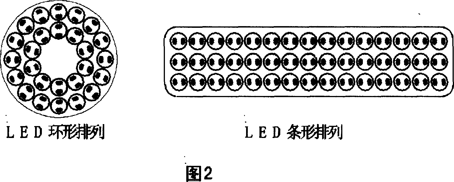
[0008] In the present invention, according to the lighting requirements, the LEDs are arranged in a ring or a strip on the circuit board, as shown in FIG. 2 .

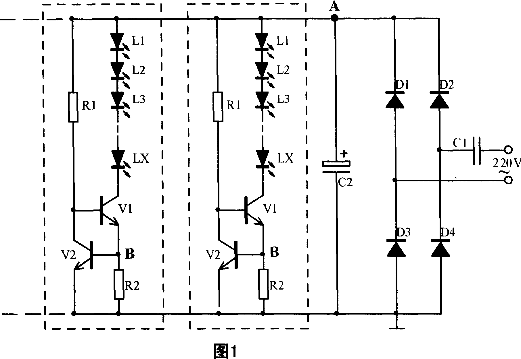
[0009] Circuit schematic diagram of the present invention as shown in Figure 1, tells about its work process below:

[0010] In the circuit, D1~D4 form a rectifier bridge. One of the two AC input ends of the rectifier bridge is connected to C1 in series, and the other end is respectively connected to the live wire and neutral wire of 220V mains power. The positive voltage output by the rectifier bridge is connected to the positive end of C2, and the rectifier bridge The output negative voltage is connected to the negative terminal of C2. The DC voltage at both ends of C2 is used as the DC power supply for the LED lighting lamp and the constant current control circuit. C1 in the circuit acts as a step-down and current-limiting function. C2 in the circuit is selected after testing, and its breakdown voltage should be a...


PUM


Abstract

The circuit thereof comprises: LED lamp, constant current control circuit, simple DC power, and overvoltage protection circuit; several LEDs are connected in series to form a cluster of LEDs; connecting one or more clusters of LEDs in parallel according to the size of power; each cluster of LEDs has a constant current control circuit; the filter capacitor either is used to make filter and or is used to make protection.

Description

technical field [0001] The invention relates to an LED illuminating lamp and a control circuit thereof. Background technique [0002] At present, LEDs are widely used in indicator lights, but not many are used for indoor and outdoor lighting. The known LED lighting lamps mostly adopt the working mode of connecting several LED lamps in series and then paralleling them, and then carry out constant current control, and also work by directly connecting the light-emitting diode arrays with opposite conduction directions to the alternating current. These two types of LED lighting lamps all have defects to varying degrees. As in the previous method of connecting multiple LED lights in series and then in parallel, and then performing constant current control, if a certain string of LEDs is disconnected, it will cause overloading of other strings, and soon all strings will burn out. The working method of directly connecting the light-emitting diode array with the opposite conductio...

Claims


Application Information

Patent Timeline
Patent Type & Authority Applications(China)
IPC IPC(8): H05B37/02H05B37/00
Inventor 田泽正赵明富郑竹林刘法治
Owner HENAN INST OF SCI & TECH
Why Eureka
Try Eureka