Mounting method for drum washing machine counter weight and mounting structure thereof

The technology of a drum washing machine and installation structure, which is applied to other washing machines, washing devices, textiles and paper making, etc., can solve the problems of increasing workload, affecting the delivery rate of the whole machine, failing to save costs, etc. Reliable installation method, the effect of saving settings

Active Publication Date: 2007-11-28
HAIER GRP CORP +1
View PDF2 Cites 12 Cited by
  • Summary
  • Abstract
  • Description
  • Claims
  • Application Information

AI Technical Summary

Problems solved by technology

The counterweight installation method disclosed in this reference document is to install a counterweight bracket in the washing machine, and inject concrete into the bracket to form a counterweight block. For a small number of washing machine manufacturers, this solution can save counterweight blocks to a certain extent. The cost of mold opening, however, for washing machine factories that need to mass-produce drum washing machines, the method of injecting concrete into each machine to form a counterweight will increase the workload on the one hand and affect the factory rate of the whole machine, and this solution will Can not achieve the purpose of saving costs

Method used


Image

  • Mounting method for drum washing machine counter weight and mounting structure thereof
  • Mounting method for drum washing machine counter weight and mounting structure thereof
  • Mounting method for drum washing machine counter weight and mounting structure thereof

Examples


Embodiment 1

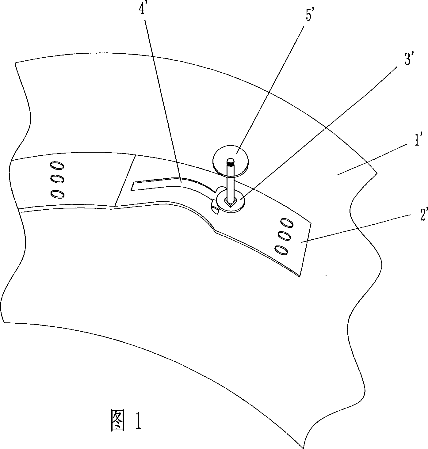
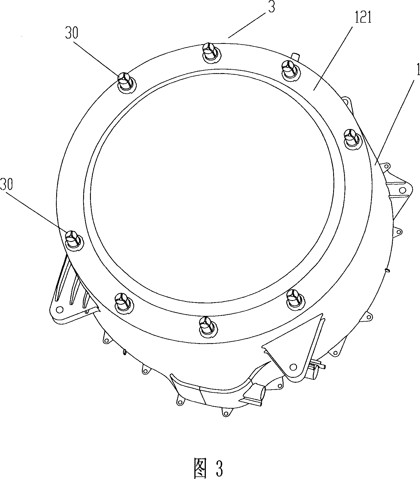
[0041] The fixing device 3 is arranged on the end surface 121 of the front end 12 of the outer cylinder, the fixing device 3 adopts an expansion bolt column, and the fastening device 4 adopts a screw; The installation through hole 21 on the top passes through the fixing device 3, and is installed and fixed on the end surface 121 of the front end 12 of the washing machine outer cylinder 1 through the fastening device 4; the fixing device 3 is at least two expansion bolt columns 30, and the fastening device 4 The fixing device 4 is a screw 40 with a diameter slightly smaller than the diameter of the expansion bolt column. The expansion bolt column 30 is divided into three parts, and the center of the expansion bolt column is provided with a screw installation hole 301 for plugging and fixing the screw 40. When the screw 41 is squeezed into the screw installation In the hole 301, the expansion bolt column 30 is pressed outwards, and the column expands outwards and presses it tight...

Embodiment 2

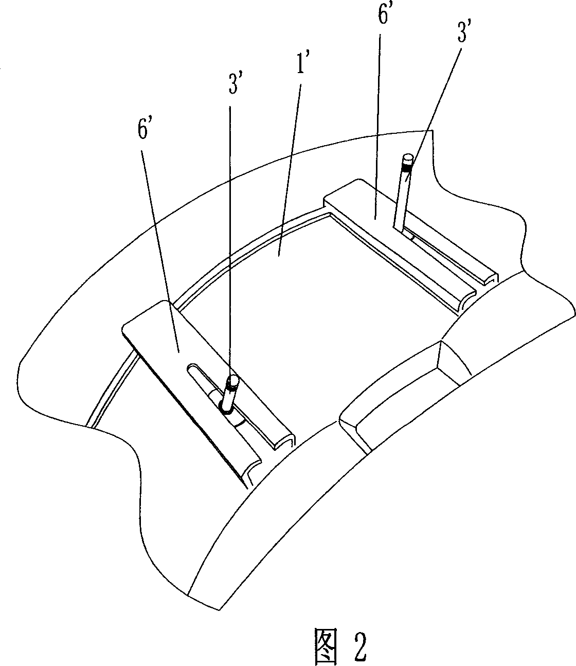
[0047] The structures of the fixing device and the fastening device are the same as those in Embodiment 1, except that the fixing device 3 is arranged on the top outer surface 11 of the washing machine tub 1 .

[0048] As shown in FIG. 7 , the expansion bolt column 3 is arranged on the top outer surface 11 of the washing machine tub 1 , and the counterweight is removed in order to clearly show the expansion bolt column and the fastening device in the figure.

[0049] Usually, when the expansion bolt column 3 is arranged on the top outer surface 11 of the washing machine tub 1, it is sufficient to arrange between 2 and 4 expansion bolt columns 30, and the counterweight can be an arc-shaped solid block, and its radian is the same as The curvature of the washing machine tub 1 matches; or, the counterweight 2 is a fixed block of any shape. In addition, the expansion bolt column 3 can also be in the form of plastic expansion anchor bolts, metal expansion anchor bolts, strong expans...

Embodiment 3

[0052] The present invention proposes a new connection method: the plug-in method combined with the deformed bolt, that is, on the basis of the existing plug-in method, the fixing device screws in Embodiments 1 and 2 are changed to those in the prior art. Hollow rivet structure, although the hollow rivet is a prior art, no one has applied this technology to the field of washing machines at present. This technical solution is adopted in the present invention, and it is applied to the connection method between the counterweight and the washing machine to obtain The utility model achieves unexpected beneficial effects, overcomes the defects of the prior art, simplifies the installation procedure and improves the installation efficiency, and the fixing firmness between the counterweight and the washing machine is better than that of the prior art.

[0053] As shown in Figure 8, Figure 8a, and Figure 8b, the counterweight 2 is installed on the boss 31 through the installation throug...


PUM


Abstract

The installing method and installing configuration of match weight block for the barrel roller washing machine, its configuration consists of the outer case of the washing machine, a weight match block on which there are installing holes. There is fixed device incorporated with case for the installing of the weight match block which is installed on the fixed device through the installing holes, and the weight match block can fix on the case of the washing machine by the tighten fixed device. This invention can obtain a more convenient installing method by the replacement of the bolt device by the swell blot on the base of no changing the current configuration of the weight match block. It can save the cost, process and working intensity largely.

Description

technical field [0001] The invention relates to an installation structure of a counterweight of a drum washing machine, and at the same time, an installation and fixing method of the counterweight with the installation structure. Background technique [0002] The drum type washing machine has a drum, which is placed in the cabinet horizontally or obliquely. The drum rotates alternately in both directions, and the clothes are loaded in the drum, and the washing water is fed into it from an external water source. When the drum rotates, the clothes and washing water in the drum repeatedly fall from above to below, thereby washing the clothes. Meanwhile, vibration and noise are generated due to the rotation of the drum during the washing operation of the drum. In order to reduce this vibration and noise, a counterweight is mounted on the outer tub supporting and placing the rotatable drum to reduce vibration and noise. For the installation structure of the counterweight, the ...

Claims


Application Information

Patent Timeline
Patent Type & Authority Applications(China)
IPC IPC(8): D06F37/00
Inventor 吕佩师李文伟秦绪松王佳
Owner HAIER GRP CORP
Why Eureka
Try Eureka