Fan system

A fan system and switch technology, applied in the direction of a single motor speed/torque control, electronic commutator, starting device, etc., can solve the problems of low power, difficult to manufacture, high cost and so on

Inactive Publication Date: 2007-11-28
DELTA ELECTRONICS INC
View PDF0 Cites 1 Cited by
  • Summary
  • Abstract
  • Description
  • Claims
  • Application Information

AI Technical Summary

Problems solved by technology

[0009] In view of the above problems, the purpose of the present invention is to provide a fan system, which is by arranging a first switch and a second switch outside the driving device, and a third switch and a fourth switch are arrange

Method used


Image

  • Fan system
  • Fan system
  • Fan system

Examples


Embodiment Construction

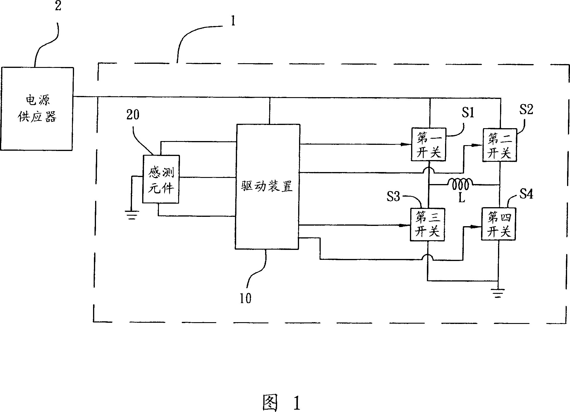
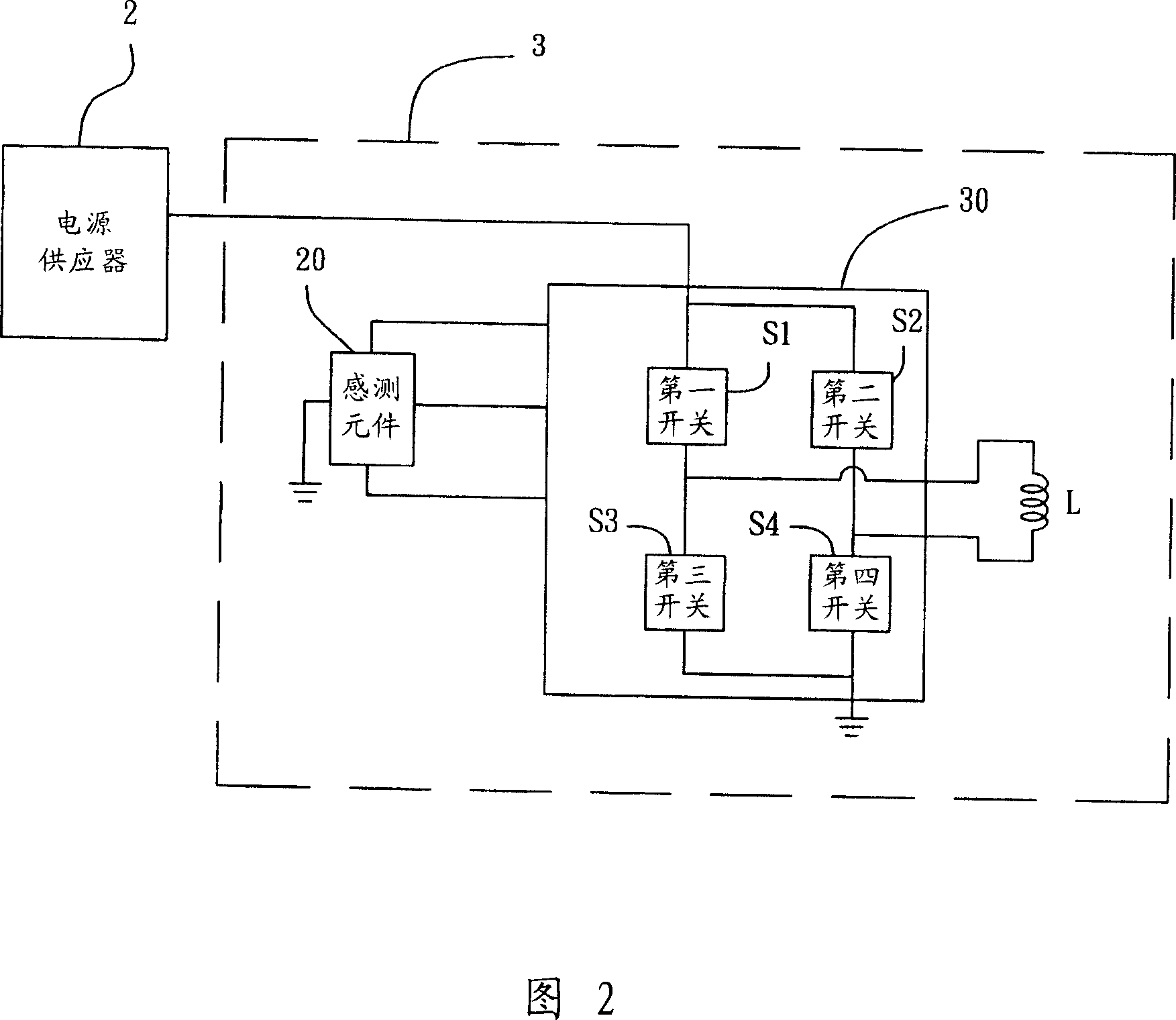
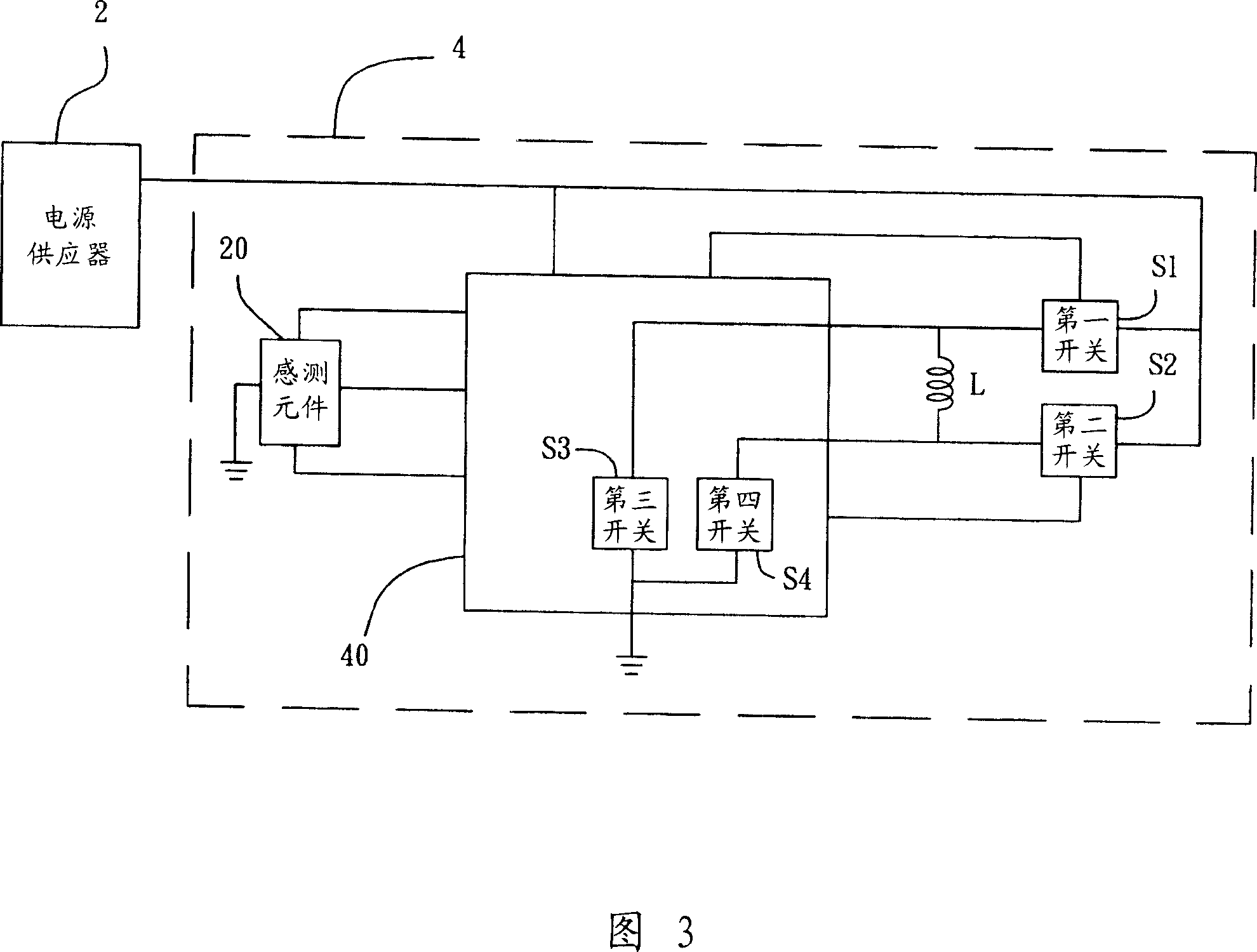
[0030] 3, the fan system 4 of the present invention is electrically connected to a power supply 2, and the fan system 4 includes: a driving device 40, a sensing component 20, a first switch S1, a second The switch S2 and a coil L. The driving device 40 is electrically connected to the power supply 2, the sensing element 20 is electrically connected to the driving device 40, and both the first switch S1 and the second switch S2 are electrically connected to the power supply at the same time. The supplier 2, the driving device 40, and the coil L are electrically connected between the first switch S1 and the second switch S2.

[0031] The driving device 40 further has a third switch S3 and a fourth switch S4, and the third switch S3 and the fourth switch S4 form a bridge with the first switch S1, the second switch S2 and the coil L connected, and the driving device 40 can control the alternating conduction of the switch, so that the current flowing through the coil L changes, so...


PUM


Abstract

The invention discloses a fan system to connect a power supplier electrically, which comprises the following parts: first switch, second switch, coil and driving device, wherein the driving device consists of third switch and fourth switch; the first, second, third and fourth switches and coil form bridged connection.

Description

technical field [0001] The invention relates to a fan system, in particular to a fan system capable of increasing output power and reducing manufacturing cost. Background technique [0002] Due to the continuous increase of the information processing capacity of the current electronic system, the heat generated is also increased accordingly. However, according to the user requirements that most electronic systems emphasize fast, continuous and uninterrupted, the heat dissipation requirements in the electronic system are getting more and more attention. There are more and more heat dissipation products derived from various products, and the most efficient and widely used fan system is currently on the market. [0003] Please refer to FIG. 1, which discloses a fan system 1, which is electrically connected to a power supply 2 to receive power. The fan system 1 is mainly composed of a driving device 10, a sensing component 20, a first A switch S1, a second switch S2, a third sw...

Claims


Application Information

Patent Timeline
IPC IPC(8): H02P6/08H02P6/16H02P6/20
Inventor 刘铭龙卓义杰吴家丰黄跃龙
Owner DELTA ELECTRONICS INC
Why Eureka
Try Eureka