
Glass substrate positioning apparatus, positioning method, edge plane polishing apparatus and edge plane polishing method

A glass substrate and positioning device technology, applied in positioning devices, grinding workpiece supports, grinding/polishing equipment, etc., can solve the problems of poor processing efficiency, difficulty in moving to the correct position, blocking member glass substrate stuck, etc. , to achieve the effects of shock mitigation, high-precision positioning, and inhibition of premature wear

Active Publication Date: 2007-11-28
NIPPON ELECTRIC GLASS CO LTD
View PDF2 Cites 21 Cited by
  • Summary
  • Abstract
  • Description
  • Claims
  • Application Information

AI Technical Summary

Problems solved by technology

[0010] However, any of the above-mentioned positioning device shown in FIGS. 6 and 7 and the position detection device disclosed in Patent Document 1 is fixed with a blocking member (a fixed roller, a fixed plate, and a reference stopper) that functions as a stopper. device), therefore, the sharp edge (cut end surface) of the glass substrate before grinding is brought into contact with the stopper member with a relatively large impact force
[0011] Therefore, it may cause the blocking member to be chipped due to the sharp edge of the glass substrate, thereby causing premature wear, the positioning of the glass substrate is unstable, or the blocking member is scratched so that the edge of the glass substrate is caught at the scratch, or Difficulty moving to the correct position, etc. so-called bad situations
[0012] Moreover, any of these devices positions the glass substrate with the abutting portion of the stopper member as a reference. Therefore, when the abutment portion of the stopper member is worn as described above, the abutment position of the glass substrate changes at one point. , so there is a risk that the positioning accuracy of the glass substrate will deteriorate
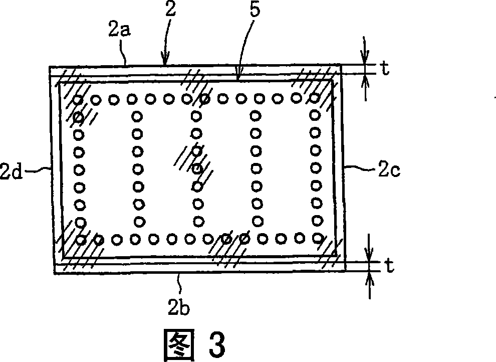
[0013] Also, as mentioned above, when the positioning of the glass substrate is hindered, for example, as shown in FIG. The grinding amount t of the substrate 20 becomes larger
In such a state, the grinding speed needs to be slowed down, and the processing efficiency is deteriorated, and the amount of grinding is uneven, so the surface quality of the ground surface is reduced.
[0014] Furthermore, since the size of the glass substrate has been increased in recent years, it is difficult to move the glass substrate smoothly, and the glass substrate is skewed. Therefore, it is also impossible to properly contact the glass substrate with the stopper by the action of the pressing member. bad situation
[0015] On the other hand, the chamfering apparatus disclosed in the above-mentioned Patent Document 2 does not position the glass substrate by contacting the rollers, but first positions the pair of rollers and then conveys the glass substrate between the two rollers. Of course, the problem in the case of positioning the glass substrate against the stopper member as described above cannot be solved.

Method used


Image

  • Glass substrate positioning apparatus, positioning method, edge plane polishing apparatus and edge plane polishing method
  • Glass substrate positioning apparatus, positioning method, edge plane polishing apparatus and edge plane polishing method
  • Glass substrate positioning apparatus, positioning method, edge plane polishing apparatus and edge plane polishing method

Examples


Embodiment Construction

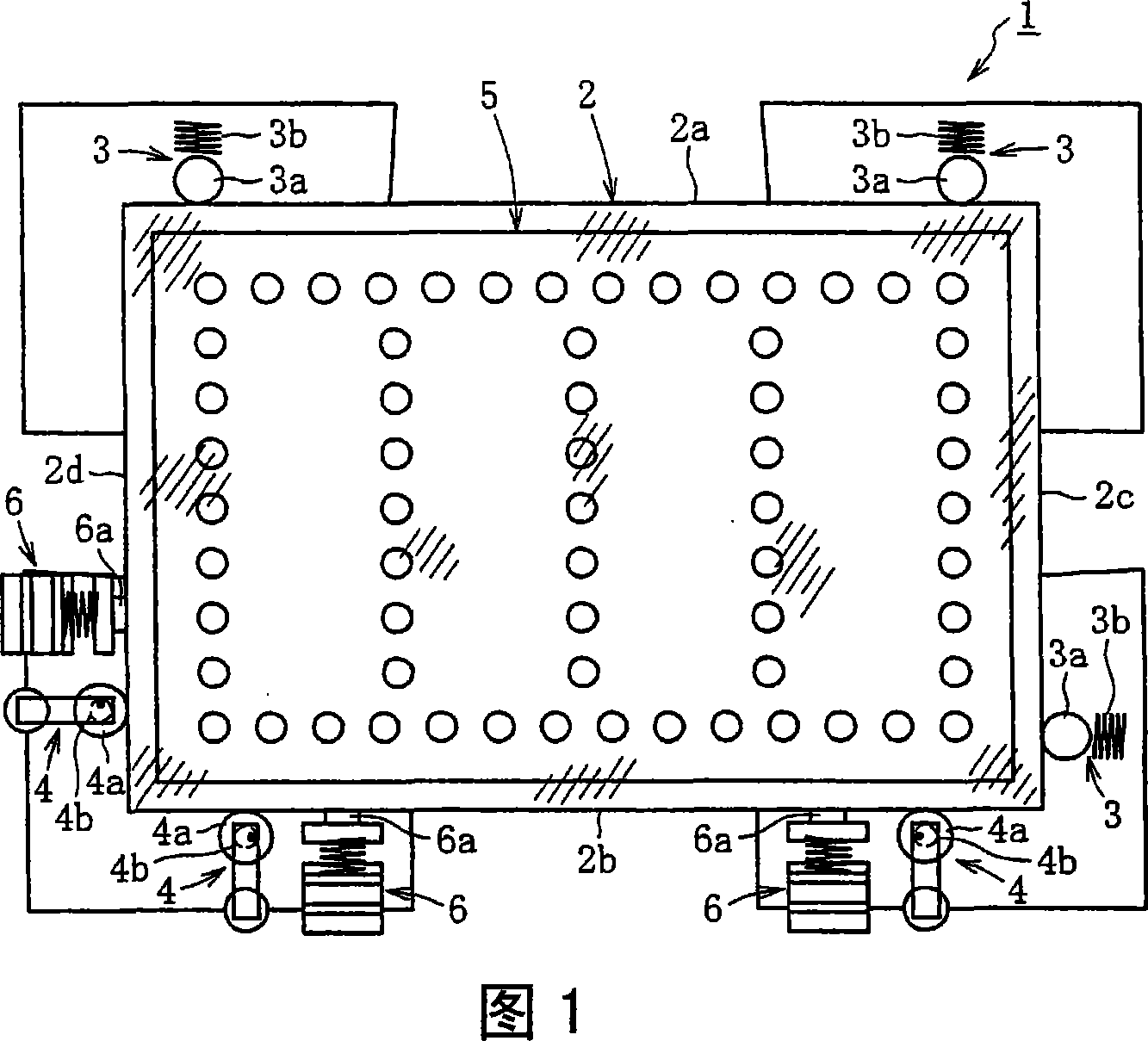
[0049] Hereinafter, embodiments of the present invention will be described with reference to the drawings. In addition, since the end surface grinding apparatus provided with the positioning device of this embodiment is the same as the structure shown in FIG. 4 and FIG. 5 already demonstrated, illustration and description are abbreviate|omitted.

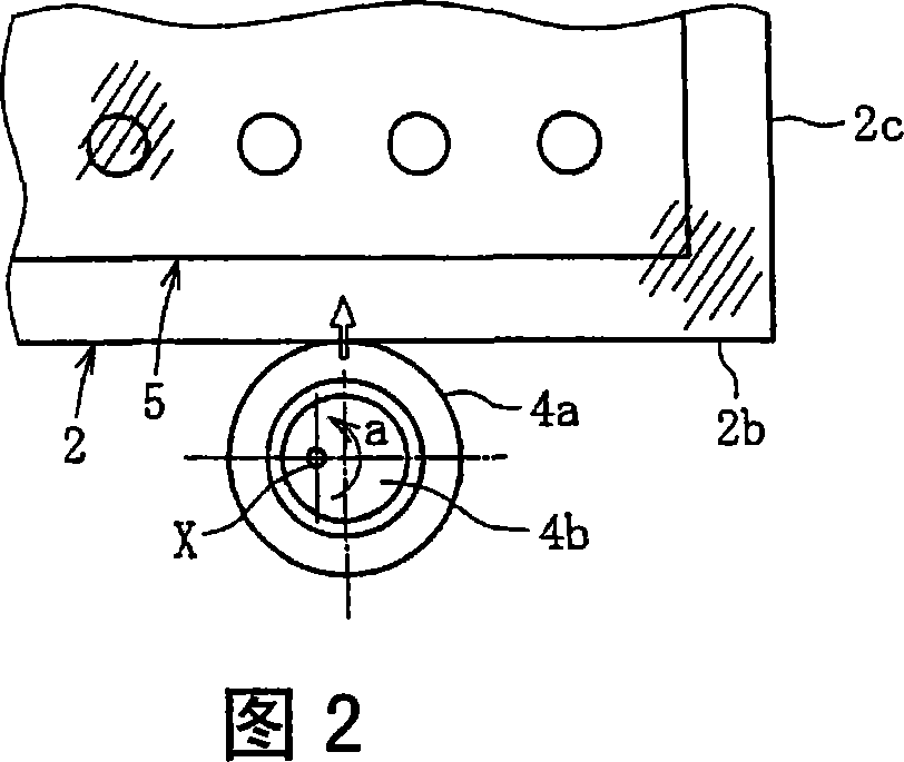
[0050] As shown in FIG. 1 , the positioning device 1 of this embodiment basically includes: a blocking member 3 capable of abutting against one side 2a (2c) of the glass substrate 2; 2d) The pressing member 4 that abuts and pushes the glass substrate 2 to the blocking member 3 side, the blocking member 3 is set to be able to move following the pushing of the glass substrate 2, and the pressing member 4 is on one side 2a (2c) of the glass substrate 2 ) is in contact with the stopper member 3, the positioning of the glass substrate 2 is performed with reference to the displacement amount of the other side 2b (2d) of the glass substrate...


PUM


Abstract

A glass substrate positioning apparatus is provided with a catching member (3) which can abut to one side (2a (2c)) of a glass substrate (2); and a pressing member (4) which can abut to other side (2b(2d)) parallel to the side (2a(2c)) and presses and moves the glass substrate (2) to a side of the catching member (3). The apparatus positions the glass substrate (2) by interactions between the catching member (3) and the pressing member (4). The catching member (3) is permitted to move by following movement of the glass substrate (2) being pressed, then, the glass substrate (2) is positioned by having as a reference an amount of displacement of the side (2b(2d)) of the glass substrate (2) caused when the glass substrate is moved by being pressed by the pressing member (4) in a status where the side (2a(2c)) of the glass substrate (2) is permitted to abut to the catching member (3).

Description

technical field [0001] The present invention relates to a positioning device and method for a glass substrate, and an end grinding device and method, and more particularly to a positioning device and a method for accurately positioning a glass substrate that needs to be held in a normal position in a normal posture, and positioning thereby An end surface grinding device and method for grinding an end surface of a glass substrate after completion. Background technique [0002] As everyone knows, when manufacturing glass panels for various image display devices such as liquid crystal displays, plasma displays, electroluminescent displays, and electroluminescent displays, the cut end faces of glass substrates, that is, glass substrates with sharp cut end faces, are processed in the production process. Grinding to obtain the required size or end face characteristics. [0003] It is customary to carry out such end surface grinding by making the grinding piece relatively move alo...

Claims


Application Information

Patent Timeline
Patent Type & Authority Applications(China)
IPC IPC(8): B23Q3/18B24B9/10B24B41/06H01L21/68B24B7/16B24B7/24B65G49/06
CPCB24B9/10H01L21/682B24B41/06B24B7/16B24B7/24
Inventor 西村直树奥村弘和山木茂
Owner NIPPON ELECTRIC GLASS CO LTD
Learn More