Method for preventing the generating of chamfer angle in the processing of corner angle

A technology of edges and corners, which is applied in the field of preventing chamfering of edges and corners during edge processing, can solve problems such as failure to meet product requirements, and achieve the effect of easy implementation and simple methods

Active Publication Date: 2007-12-05
BYD CO LTD
View PDF0 Cites 0 Cited by
  • Summary
  • Abstract
  • Description
  • Claims
  • Application Information

AI Technical Summary

Problems solved by technology

However, when the semicircular concave surface 6 is polished, it is very easy to produce a chamfer R at the edge of the corner formed by the intersection of the plane 5 and the semicircular concave surface 6.
The appearance of chamfer R cannot meet the requirements of the product

Method used


Image

  • Method for preventing the generating of chamfer angle in the processing of corner angle
  • Method for preventing the generating of chamfer angle in the processing of corner angle
  • Method for preventing the generating of chamfer angle in the processing of corner angle

Examples


Embodiment Construction

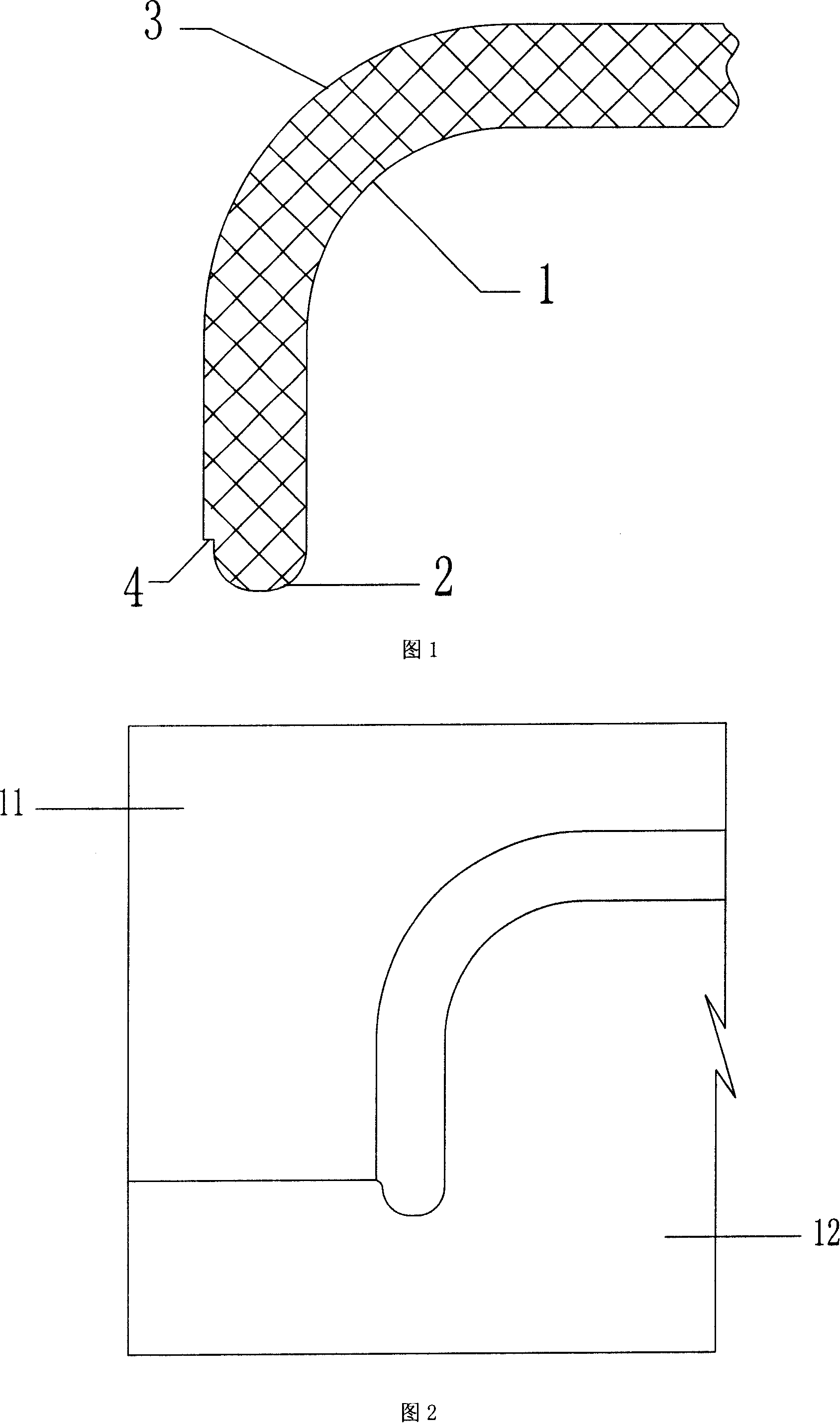
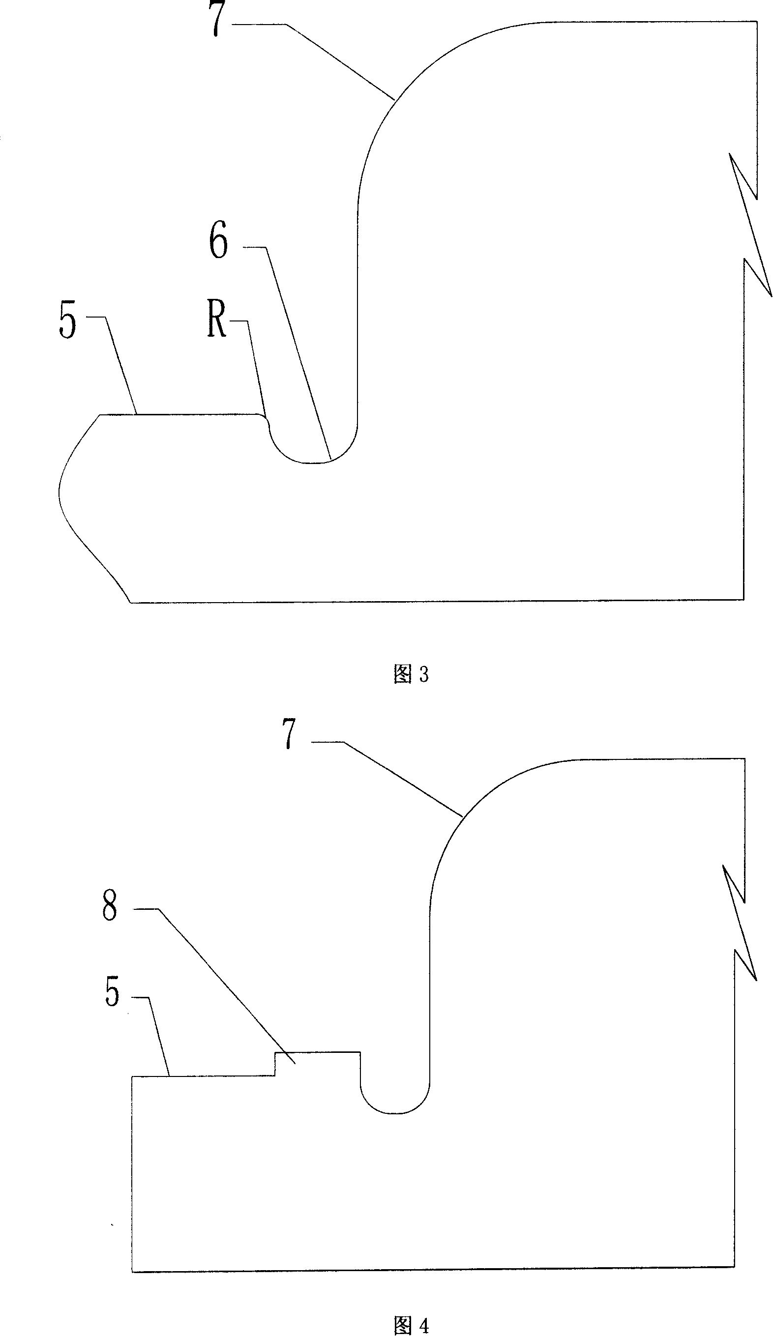
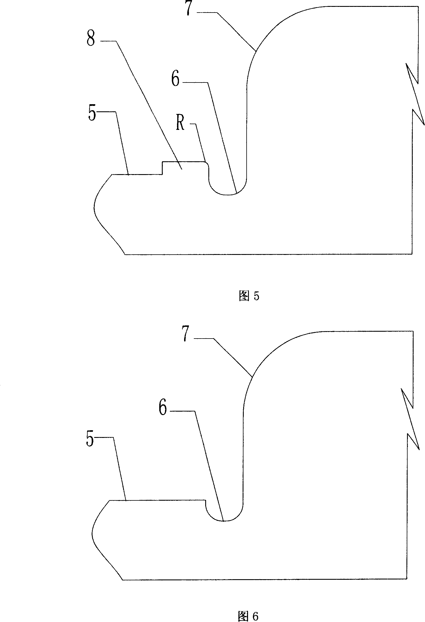
[0022] Fig. 4, Fig. 5 and Fig. 6 have shown the process of processing a kind of product part (fixed mold core shown in Fig. 2) according to the method of the present invention.

[0023] When processing the fixed die core in Figure 2, first process the fixed die core blank into the shape shown in Figure 4, and reserve a boss along the right edge of the surface 5 when milling the surface 5 (first surface) 8. The height of the boss 8 is 0.3 mm, and the width of the boss 8 in the direction extending from the right edge to the center of the surface 5 (the first surface) is 3.0 mm.

[0024] Then the semicircular concave surface 6 (second surface) of the fixed mold core shown in Fig. 4 is polished until its surface finish meets the requirements. As shown in FIG. 5 , at this time, a chamfer R is formed at the edge position of the upper right corner of the boss 8 due to polishing.

[0025] Then the boss 8 is milled away, and the chamfer R will not appear at the edge position where the...


PUM


Abstract

The method of avoid chamfering during machining edge includes the following steps: retaining one lug in the first surface of the edge with relatively low smoothness, polishing the second surface to reach the required surface smoothness, and finally leveling the first surface via eliminating the lug. The method is simple and practical, and is suitable for machining edge with only surface possessing relatively high smoothness requirement.

Description

technical field [0001] The invention relates to a method for processing corners, in particular to a method for preventing chamfering of edges during corner processing. Background technique [0002] Fig. 1 is a product part, the concave surface 1 and the semicircular convex surface 2 are the front of the part, which require a high surface finish. At the same time, it is required to form a stepped surface 4 between the semicircular convex surface 2 and the convex surface 3 (the surface finish requirement is relatively low), and the angle between the stepped surface 4 and the semicircular convex surface 2 is a right angle. The part is manufactured using injection molding. Fig. 2 shows the positional relationship between the movable mold core 11 and the fixed mold core 12 during the injection molding process. The fixed mold core is shown in Figure 3. When processing the fixed mold core, the intersection of the plane 5 and the semicircular concave surface 6 should be processed ...

Claims


Application Information

Patent Timeline
Patent Type & Authority Applications(China)
IPC IPC(8): B24B29/02
Inventor 戚子沛
Owner BYD CO LTD
Why Eureka
Try Eureka