Mechanical flexibility space buttjunction platform

A technology of space docking and docking platform, applied in the direction of workbench, manufacturing tools, etc., can solve the problems of workpiece damage, inflexibility of docking platform, and misalignment of the geometric center of slide rail and chute, so as to avoid injury and improve space docking. Quality and docking effect, easy operation control and assembly and disassembly maintenance effect

Inactive Publication Date: 2007-12-05
CHONGQING UNIV
View PDF0 Cites 18 Cited by
  • Summary
  • Abstract
  • Description
  • Claims
  • Application Information

AI Technical Summary

Problems solved by technology

[0003] However, it is not comprehensive to consider the exact alignment between the workpiece and the chute. After the workpiece has been accurately aligned, it is in the rising stroke. Due to various working conditions, such as vibration, force, etc., or Human factors act on the workpiece, resulting in a slight deviation of the workpiece during the rising stroke, and the geometric centers of the slide rail and the chute do not coincide, which directly affects the assembly a

Method used


Image

  • Mechanical flexibility space buttjunction platform
  • Mechanical flexibility space buttjunction platform
  • Mechanical flexibility space buttjunction platform

Examples


Embodiment 1

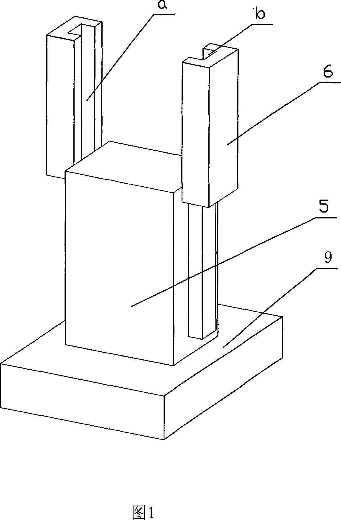
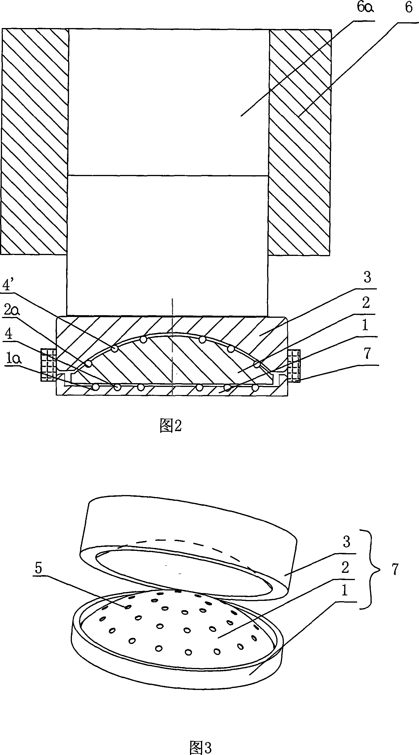
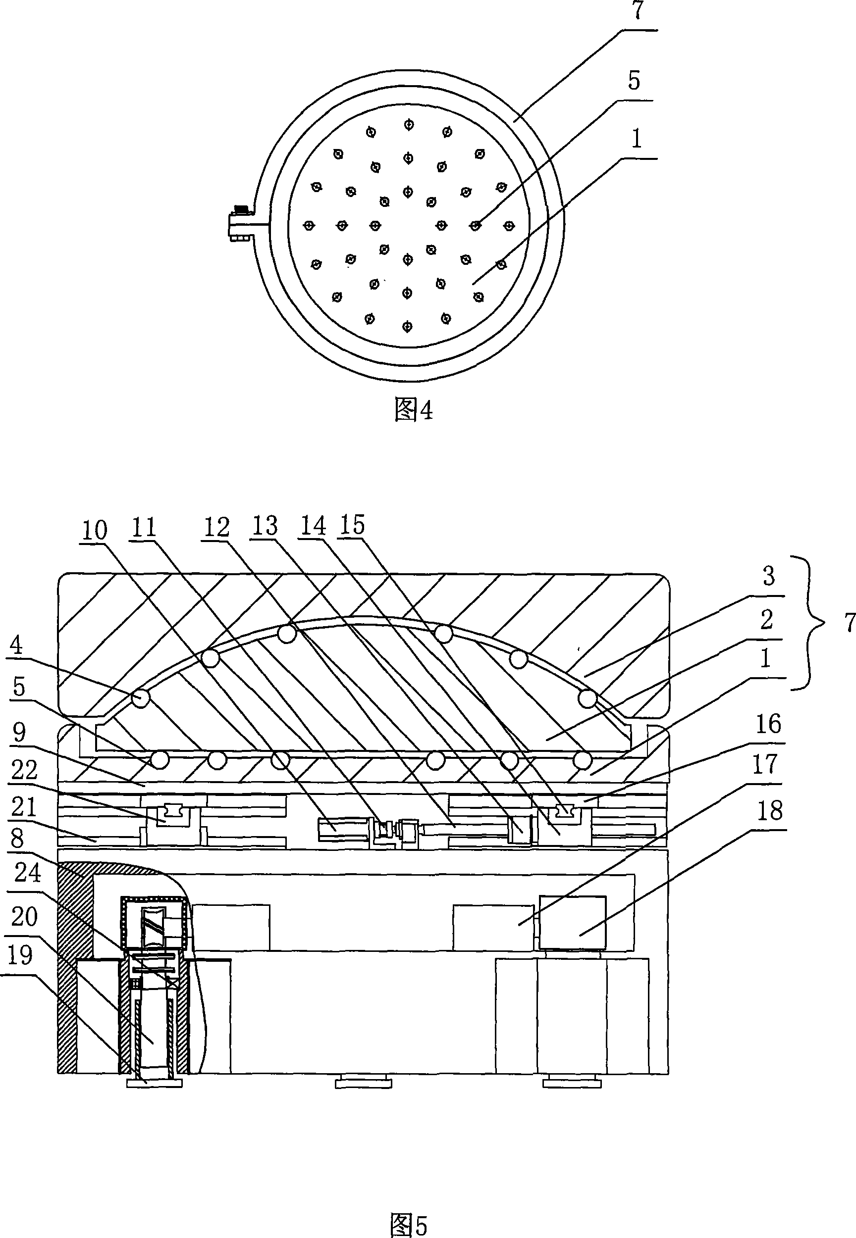
[0037]As shown in Figures 2, 3, and 4: a mechanical flexible space docking platform is provided with a mechanical flexible assembly platform installed on a mechanical self-adjusting docking platform, wherein the mechanical flexible assembly platform consists of a base 1, a joint Body 2 and floating body 3, wherein the upper end of the base 1 is provided with a circular groove, and spherical pits 1a are evenly distributed in the circular grooves, balls 4 are installed in the spherical pits 1a, and the joint body 2 is a small A semi-spherical body, the bottom plane of the small semi-spherical body is located in the circular groove of the base 1 and contacts the ball 4, and spherical pits 2a are evenly distributed on the surface of the spherical cap, and the spherical pits 2a are equipped with The ball 4' covers the floating body 3 above the joint body 2, and the bottom surface of the floating body 3 is provided with an arc-shaped groove compatible with the surface of the spherica...

Embodiment 2

[0058] This embodiment 2 is consistent with embodiment 1 structure, and its difference is:

[0059] The joint body 2 is a small semi-spherical body, and the bottom plane of the small semi-spherical body is located in the circular groove of the base 1 and is in sliding contact with it.

Embodiment 3

[0061] This embodiment 3 is consistent with embodiment 1 structure, and its difference is:

[0062] The joint body 2 is covered with a floating body 3 , and the bottom surface of the floating body 3 is provided with an arc-shaped groove adapted to the surface of the spherical cap of the joint body 2 , and is in sliding contact with the joint body 2 .

[0063] Its working principle is:

[0064] The workpiece 5 is installed on the upper surface of the floating body 3, and the workpiece 5 extends into the cavity 6a of the docking body 6 to be docked with it. The two can be over-fit, interference fit or clearance fit. During the alignment stroke Torsion occurs when a slight deviation occurs. When the workpiece 5 and the floating body 3 are squeezed, the workpiece 5 drives the floating body 3 to rotate and slide at any angle on the joint body 2 in the direction of the force. At the same time, it can also drive the joint Body 2 slides on base 1 . The whole docking process can also...


PUM


Abstract

The present invention discloses one kind of mechanical flexible spatial butt-jointing platform, and features that the mechanical flexible spatial butt-jointing platform has one mechanical flexible assembling platform comprising one pedestal, one joint body and one floating body. The pedestal has one circular groove in the upper end and balls distributed homogeneously inside the groove; the joint body is one truncated sphere, whose bottom plane is located inside the circular groove and contacted with the balls in the groove and spherical crown possesses homogeneously distributed balls; and the floating body covering the joint body has arced groove in the bottom surface to contact with the balls in the joint body. The present invention has the obvious effect of self-adaptive regulating function to ensure successful spatial butt-jointing with high quality and small torsional force.

Description

technical field [0001] The invention belongs to the technical field of space docking, and in particular relates to a mechanically flexible space docking platform suitable for space docking. Background technique [0002] Existing industries have higher and higher requirements for space docking technology, such as workpiece alignment in high-precision industrial manufacturing, space station alignment, pipeline docking in medical and chemical engineering, and circuit connection in network electronic technology, etc., which affect the docking accuracy. An important factor is the relative parallelism between the approaching surfaces of the two objects. Assembly, machining, or wedging of the object itself can cause non-parallelism. The first thing to consider in the assembly process is the alignment between the two objects to be assembled. As shown in Figure 1, it is often necessary to fix the workpiece on the docking platform in engineering, and then push the workpiece into the...

Claims


Application Information

Patent Timeline
IPC IPC(8): B25H1/14B25H1/02
Inventor 谢志江朱小龙孙红岩陈平王雪欧阳奇徐新来李梦奇郭煜敬叶凡王侃倪卫
Owner CHONGQING UNIV
Why Eureka
Try Eureka