
Fan type pneumatic power executor

A pneumatic actuator, fan-shaped technology, applied in the field of actuators, can solve the problems of high manufacturing cost and maintenance cost, increased wear of gears and racks, no way to achieve accurate control, etc., to achieve easy travel, no delay in transmission, The result is a simple effect

Active Publication Date: 2007-12-05
JINAN GAOSHI MACHINERY
View PDF0 Cites 0 Cited by
  • Summary
  • Abstract
  • Description
  • Claims
  • Application Information

AI Technical Summary

Problems solved by technology

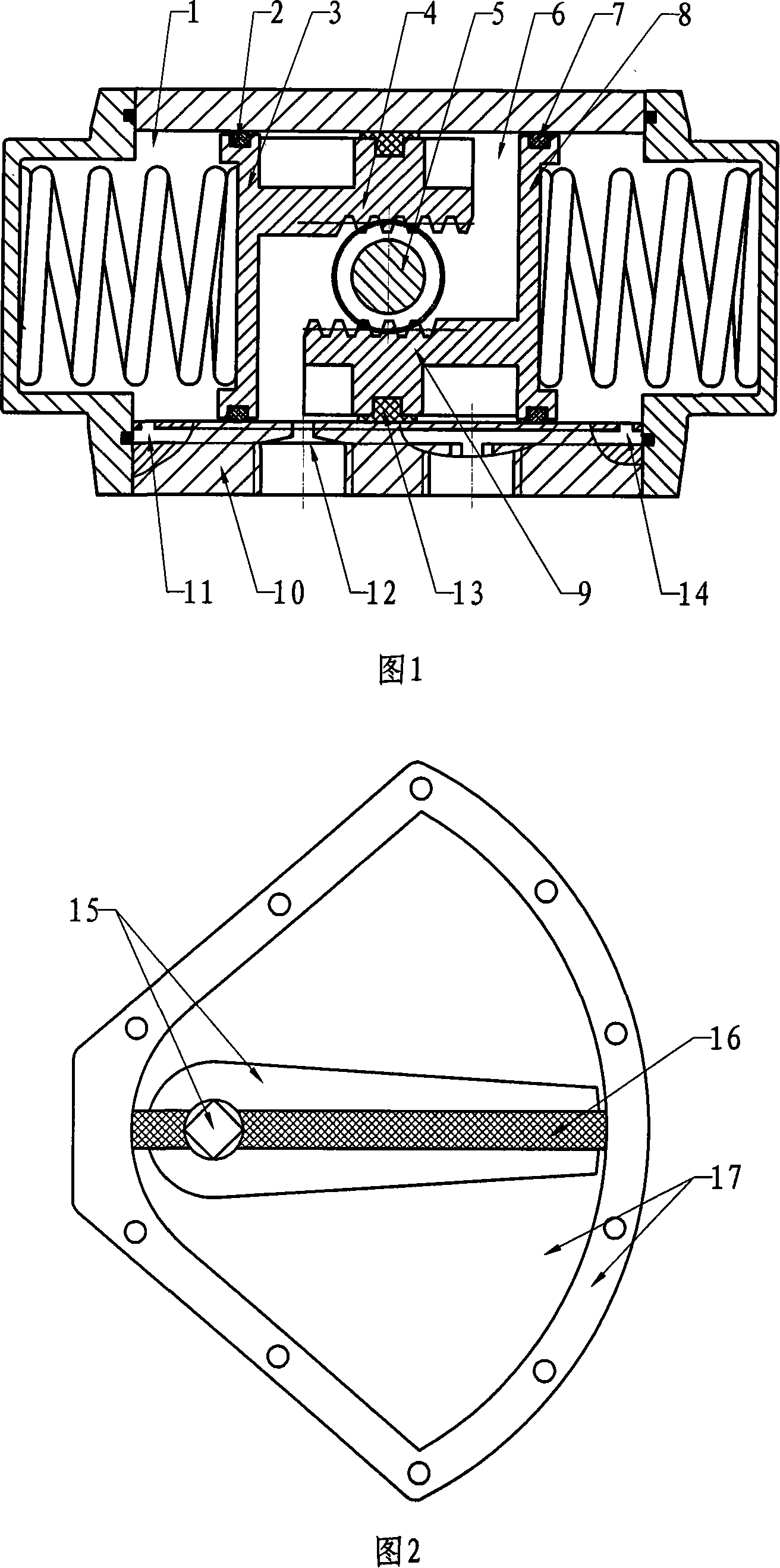
[0004] Its defects are as follows: 1. The transmission adopts rack and gear transmission, so in the transmission process, there must be a transmission hysteresis phenomenon. (13) The wear is serious, and the hysteresis phenomenon will be more obvious, especially when used in proportional control valves, there is no way to achieve accurate control
2. Because the traditional O-ring is used, as the wear of the O-ring increases, the sealing performance will gradually decrease
3. Because it is a mechanical transmission, it increases power consumption and reduces transmission efficiency
4. Because the rack and pinion drive, and the piston and the cylinder need to be sealed, all the matching parts need to be processed, and the manufacturing cost is high
[0006] It has the following defects: 1. The dynamic sealing ring added on the rotor is used to form a sealing structure with the inner chamber of the cylinder. During use, the dynamic sealing ring will inevitably wear out. To achieve a perfect seal of the dynamic sealing ring, there are many parts and it is difficult to manufacture. Costs and repairs are high
2. The inner cavity of the upper and lower cylinders is also used as the sealing surface, which must also be processed very smooth and flat, which greatly increases the manufacturing cost
3. The center shaft is a non-ISO structure, which cannot be directly assembled with the valve, and brackets and connectors must be added

Method used


Image

  • Fan type pneumatic power executor
  • Fan type pneumatic power executor
  • Fan type pneumatic power executor

Examples


Embodiment 1

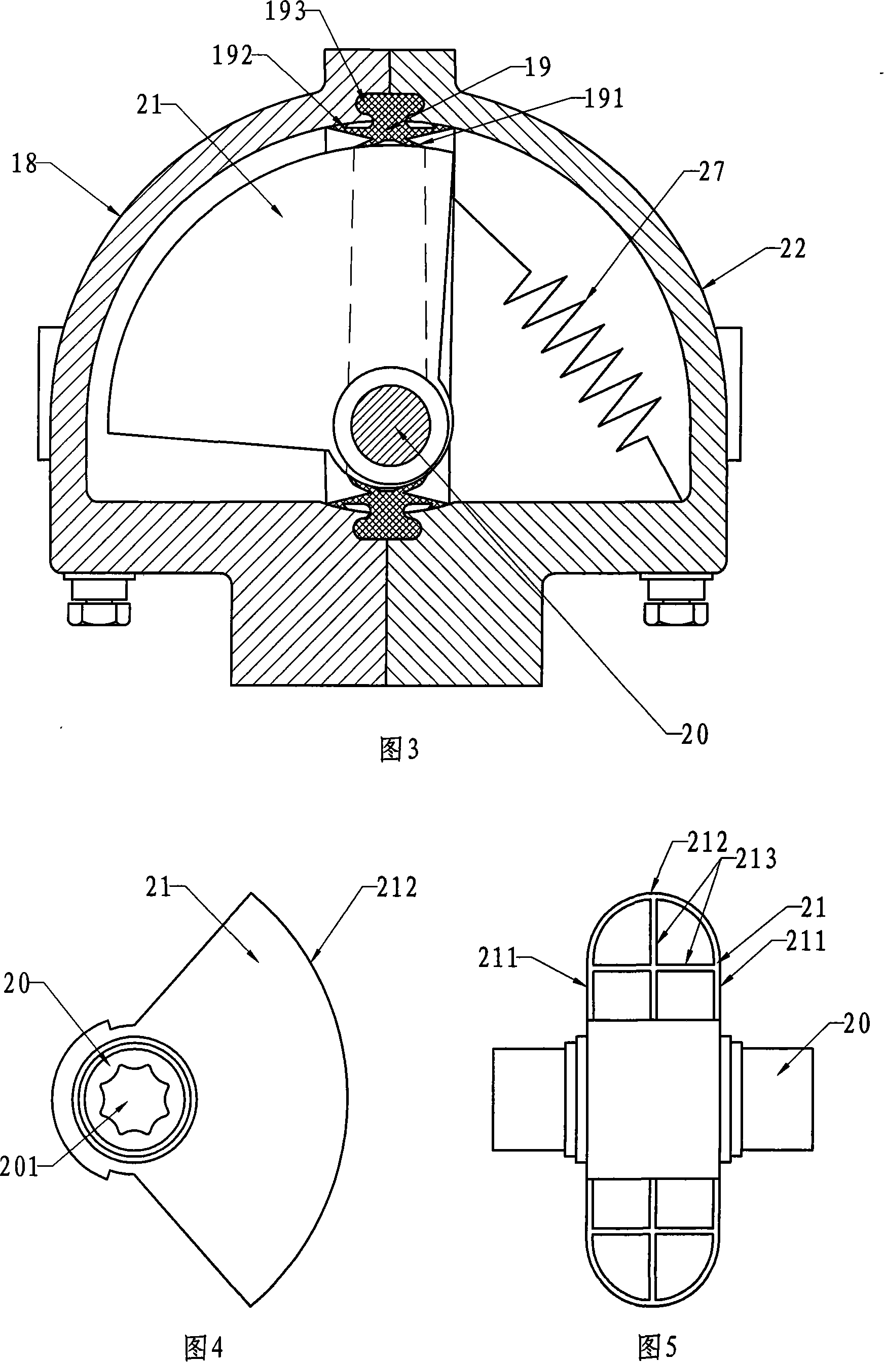
[0029] Embodiment 1: As shown in FIG. 3 , the housing of the fan-type pneumatic actuator consists of a left outer housing 18 and a right outer housing 22 . The two casings are made of plastic steel, and are molded by one injection injection molding machine, with good mechanical properties, good corrosion resistance and low cost. The structure and size of the two shells are identical, and the left shell 18 rotates 180° to be the right shell 22, so that a pair of molds can produce the whole shell. The production cost is further reduced.

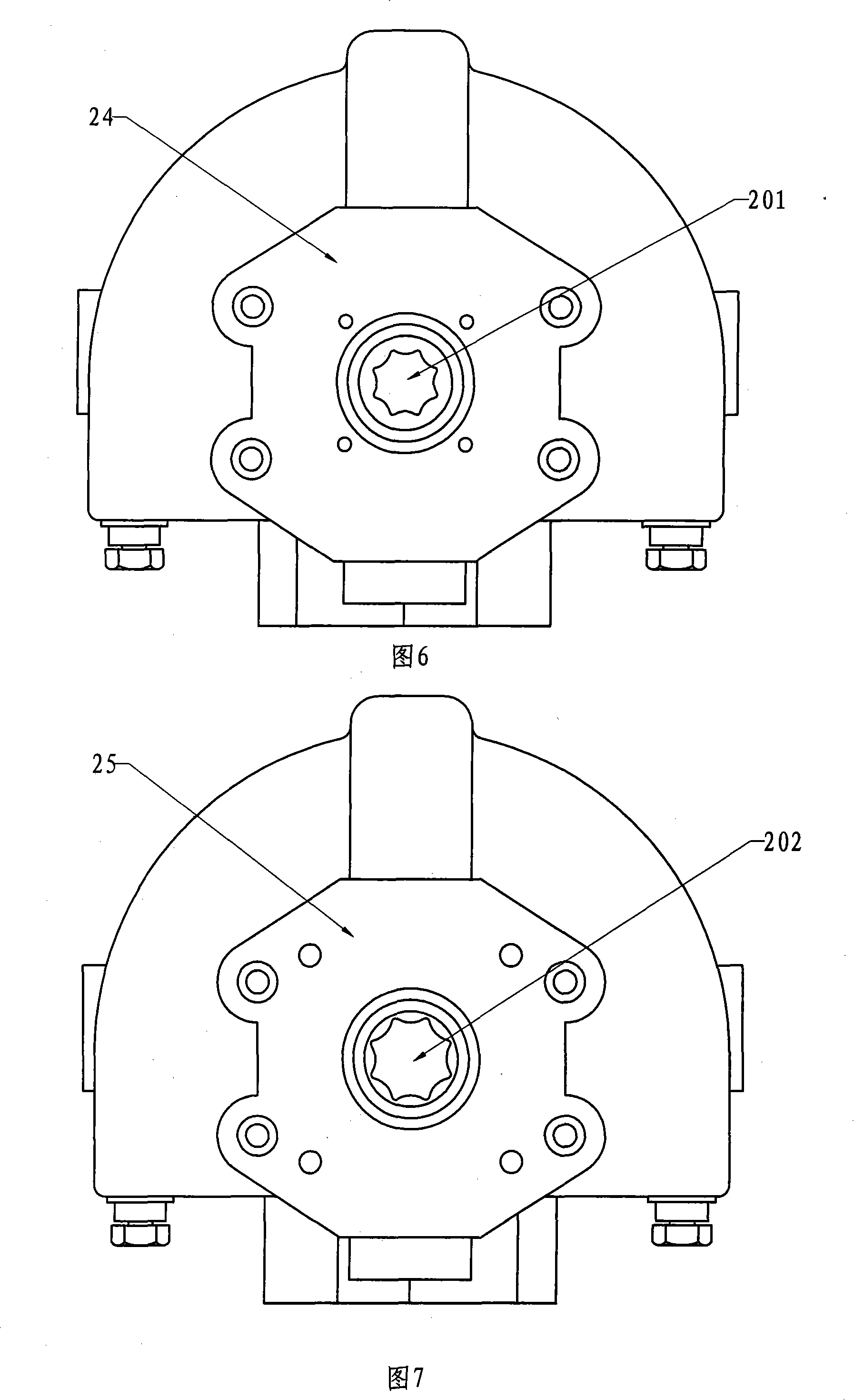
[0030] The housing is provided with a rotor 21, as shown in Figure 4 and Figure 5, the rotor is a hollow sector, the hollow part is provided with reinforcing ribs 213, located at the top of the rotor 21 and the busbar of the curved surface 212 connected to the fan-shaped surfaces 211 on both sides for the arc. The two ends of the central axis 20 of the actuator are respectively provided with a shaft hole 201, 202, which allows the actuator to...

Embodiment 2

[0036] Embodiment 2: As shown in FIG. 10 , the difference from Embodiment 1 is that in this embodiment, a helical spring returner 26 is used instead of the return spring 27 in Embodiment 1, which can also realize the function of resetting the rotor. The homing device is located outside the housing, and one end of the helical spring 261 of the homing device is fixed on its main shaft, and the other end is fixed on the housing of the homing device; the main shaft of the homing device is connected to the central axis of the actuator. The helical spring is the prior art, and the structure of the return device is relatively common in the mechanical field, and it is easy for those skilled in the art to realize it, so it will not be repeated here.

[0037] Due to the long life of the helical spring can reach two million times. Moreover, the energy consumption is low, and the loss of about 10% of the output torque attenuation from the start to the closing stroke, so the preferred embo...


PUM


Abstract

A kind of fan type pneumatic actuator belongs to control valve switch contains external shell, medial axis, rotor and sealing device installing in the external shell body. It has characteristics as that, then rotor is fan type, sealing device is a fixed seal ring which contains rotor seal blade and shell body seal blade. The rotor blade is on the surface of seal ring medial cling to the rotor. The body seal blade is on the inner surface of seal ring lateral cling to shell body. Both sides of rotor seal blade and shell body seal blade setting as '>', '<'type. Both sides of shell body seal blade peripheral setting lug boss. Seal ring fixed on binding surface of two parts of shell. The invention has low energy consumption, simple structure, less components, low cost, is suitable for switch 90 degree of automatic control valve.

Description

technical field [0001] The invention relates to an actuator, in particular to a pneumatic actuator. Background technique [0002] In some automatic control industries, especially in the fields of petrochemicals and food and pharmaceuticals, in order to improve efficiency and realize industrialized automatic production enterprises, pneumatic actuators are used to automatically control valves and other equipment that switch 90 degrees. [0003] As shown in Figure 1: the traditional rack-type pneumatic actuator has a cylinder body (10), and a vent hole (12) is provided in the center of the body to communicate with the middle chamber (6) of the cylinder. Two ventilation holes (11, 14) are provided at both ends, communicating with the outer chamber (1). There are two pistons (3,8) in the cylinder body (10), and the pistons (3,8) and the racks (4,9) are integrated. An O-shaped sealing ring (2, 7) is embedded on the outer circumference of the piston, which divides the cylinde...

Claims


Application Information

Patent Timeline
Patent Type & Authority Applications(China)
IPC IPC(8): F16K31/12
Inventor 卢国珍
Owner JINAN GAOSHI MACHINERY
Learn More