Stamper attaching apparatus and thermal transfer press machine

A technology for installing devices and pressure equipment, applied to other household appliances, optical components, household appliances, etc., can solve problems such as inability to ensure fluid passages, heating of metal molds, poor cooling efficiency, and long forming cycles, and achieve manufacturing. Simple, maintain stable performance, and simplify the composition

Inactive Publication Date: 2007-12-05
KOMATSU SANKI +1
View PDF2 Cites 7 Cited by
  • Summary
  • Abstract
  • Description
  • Claims
  • Application Information

AI Technical Summary

Problems solved by technology

That is to say, conversely, the fluid passages must be formed avoiding the formation positions of the through-holes, so there is a problem that a sufficient number of fluid passages cannot be ensured, and the heating and cooling efficiency of the metal mold deterio

Method used


Image

  • Stamper attaching apparatus and thermal transfer press machine
  • Stamper attaching apparatus and thermal transfer press machine
  • Stamper attaching apparatus and thermal transfer press machine

Examples


Embodiment Construction

[0028] Hereinafter, an embodiment of the present invention will be described with reference to the drawings.

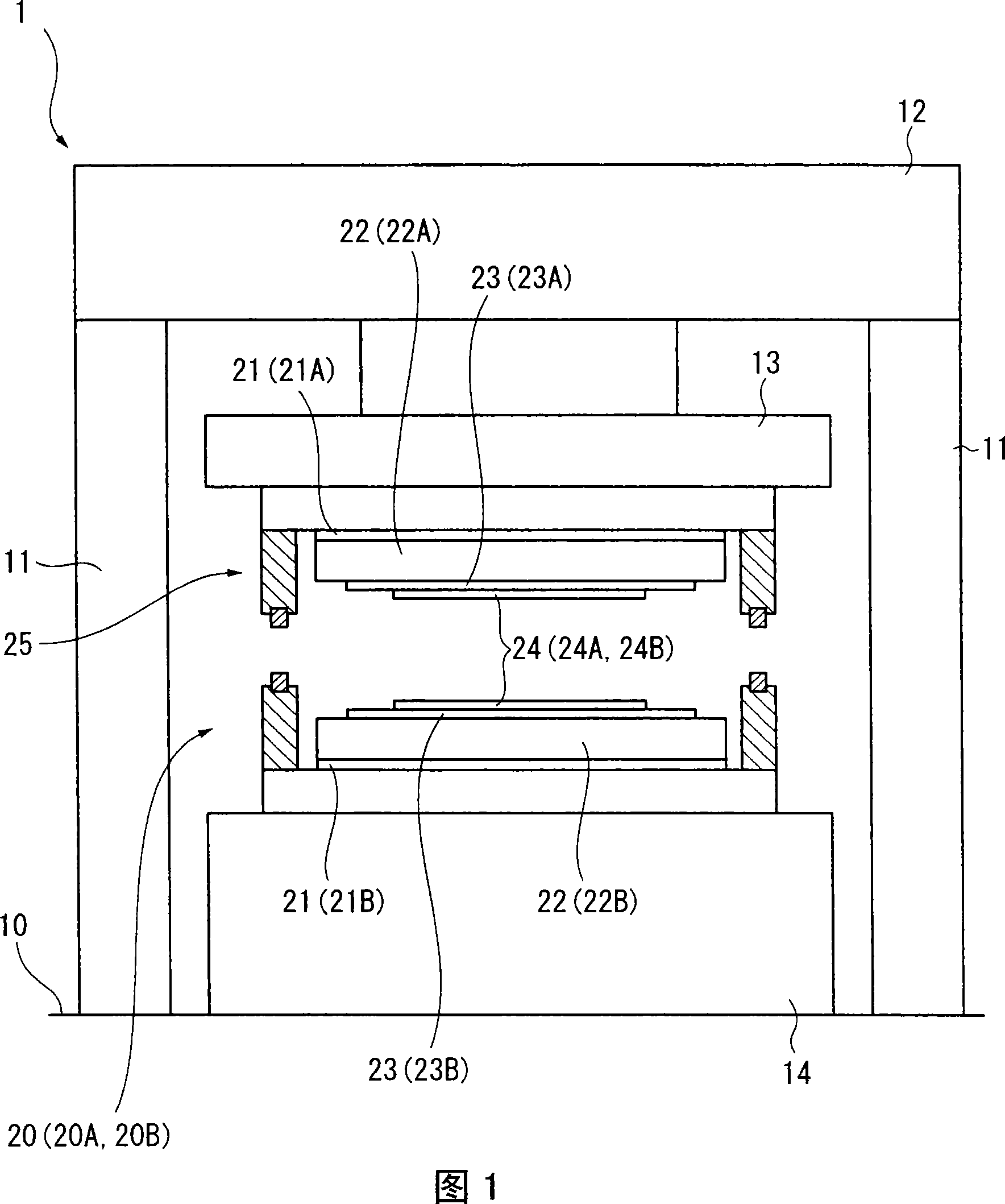
[0029] FIG. 1 is a front view showing a thermal transfer pressure device 1 according to an embodiment of the present invention. In this embodiment, the thermal transfer pressure device 1 is a device for manufacturing a light guide plate used in a backlight of a liquid crystal display by thermally transferring a concave-convex pattern onto a substrate.

[0030] In Fig. 1, the thermal transfer pressure device 1 includes: 4 columns 11 (two of which are illustrated in Fig. 1 ) erected on the base 10, a beam 12 arranged on the column 11, and a beam 12 arranged below the beam 12. The slide block 13, the cushion block 14 opposite to the slide block 13 and arranged on the base 10, the stamper installation device 20 (20A) which is arranged under the slide block 13 and installs the stamper 24 (24A), is arranged on the cushion block 14 and a stamper mounting device 20 (20B) for...


PUM


Abstract

A die mounting device (20 (20A, 20B)), in which through holes (231 (231A, 231B)). The through hole (231 (231A, 231B)) is communicated with the communication groove (232 (232A, 232B)), so that it is connected with the suction hole (222 (222A, 222B) on both sides of the temperature regulating plate (22 (22A, 22B)). )) connected. Since the entire surface of the stamper ( 24 ( 24A, 24B)) can be sucked and held, the central portion of the stamper ( 24 ( 24A, 24B)) can be prevented from floating. In addition, the dies (24 (24A, 24B)) are in close contact with the temperature control plate (22 (22A, 22B)) via the die holders (23 (23A, 23B)), so that the heating and cooling efficiency can be optimized. .

Description

technical field [0001] The invention relates to a stamper installation device and thermal transfer pressure equipment equipped with the stamper installation device. Background technique [0002] In recent years, a thermal transfer pressure device has been developed that heats and presses a stamper with fine unevenness on a resin plate formed in one pass, thereby making the unevenness of the stamper The pattern is transferred to the surface of the resin plate (for example, refer to Patent Document 1). In this thermal transfer pressure device, an air passage is formed on the mold to attach the stamper to the mold, and the stamper is attracted to the mold by sucking the peripheral portion of the stamper from the air passage. [0003] However, this thermal transfer pressure device sucks the peripheral part of the stamper, so the central part cannot be sucked well, causing the stamper to float, and the central part of the stamper cannot be sufficiently heated. Therefore, good t...

Claims


Application Information

Patent Timeline
IPC IPC(8): B29C59/02B29C33/02B29C33/30B29L11/00
CPCB29C59/002B29C33/306B29C59/02B29C33/02B29C33/30
Inventor 三吉宏治新谷俊哉箕西干夫
Owner KOMATSU SANKI
Why Eureka
Try Eureka