Control method and control apparatus for variable wavelength optical filter

a control method and control apparatus technology, applied in multiplex communication, electromagnetic repeaters, instruments, etc., can solve the problems of deterioration of the rejection level, high reliability and flexibility of the network, and increase the cost of the node on a larger scale, so as to achieve reliable and stable performance

Inactive Publication Date: 2005-09-20
FUJITSU LTD
View PDF25 Cites 5 Cited by
  • Summary
  • Abstract
  • Description
  • Claims
  • Application Information

AI Technical Summary

Benefits of technology

[0021]The present invention has been accomplished in view of the above problems, with an object of providing a control method and a control apparatus for a variable wavelength optical filter, which can reliably and stably control drive conditions of the variable wavelength optical filter, independent of the number of wavelengths to be selectively separated in collective.
[0026]According to such a control method for a variable wavelength optical filter, for the monitor signal corresponding to light reception power of monitor light taken out from the variable wavelength optical filter, an alternating current component showing only a variation component (difference) thereof is extracted, and the drive condition is controlled based on a level change of the alternating current component, so that the control of the drive condition of the variable wavelength optical filter can be performed reliably and stably, independent of the number of wavelengths to be selectively separated in collective.
[0027]Furthermore, in the aforementioned control method for a variable wavelength optical filter, it is preferable to extract, from the extracted alternating current component, only a level variation component corresponding to a change in drive condition of the variable wavelength optical filter, and to control the drive condition of the variable wavelength optical filter based on the extracted level variation component. As a result, a possibility of confusion between a level variation in the monitor signal caused by changing the drive condition of the variable wavelength optical filter, and a level variation in the monitor signal caused by other factors is reduced. Hence, it becomes possible to perform the control of the drive condition of the variable wavelength optical filter more reliably and stably.
[0028]Furthermore, in the aforementioned control method for the variable wavelength optical filter, a direct current component of the monitor signal may be extracted, to control the drive condition of the variable wavelength optical filter based on a level of the extracted direct current component. As a result, it becomes possible to perform the control corresponding to a variation component of the monitor light power based on the level change of the alternating current component, and at the same time to execute the control corresponding to an absolute value of the monitor light power based on the level of the direct current component. Hence, it becomes possible to perform the control of the drive condition of the variable wavelength optical filter more flexibly.
[0032]In such a control apparatus for a variable wavelength optical filter, the monitor light taken out from the variable wavelength optical filter, is received by the light reception section, wherein a monitor signal corresponding to the light reception power is generated, and the alternating current component showing only the variation component (difference) of the monitor signal, is extracted by the alternating current component extraction section. Then, the drive condition of the variable wavelength optical filter is controlled by the control section based on the level change of the extracted alternating current component so that the control of the drive condition of the variable wavelength optical filter can be reliably and stably performed, independent of the number of wavelengths to be selectively separated in collective.

Problems solved by technology

Furthermore, since services used by users are becoming multifarious, there is a demarid to simultaneously realize an economical network having high reliability and flexibility.
However, in the case of increasing information processing ability of a network node following higher speed of transmission signal and larger capacity, in conventional photoelectric conversion and electrical switching methods, there is caused an increase in node cost and a larger scale.
If the transmission central wavelength of the variable wavelength optical filter does not coincide with the wavelengths of optical signals, deterioration of rejection level, erroneous blocking of optical signals of other channels or the like, occurs in the block processing.
Moreover, an increase in insertion loss, erroneous dropping of optical signals of other channels, or the like, in the variable wavelength optical filter, occurs in the drop processing, and this is fatal to the results of processing executed at the OADM nodes.
Moreover, for a variable wavelength optical filter itself, fluctuations occur in the transmission central wavelength due to a change with time, environmental variations, control errors or the like.
However, if the number of wavelengths for collective processing is increased so that the number of monitor lights to be collectively output is increased, power of the monitor lights other than wavelengths intended to be tracking controlled is increased, and the components thereof become noise for error signals.
Therefore, in the case where detection accuracy of error signals is reduced due to an increase in the number of wavelengths for collective processing, there is caused a possibility that the tracking control of a variable wavelength optical filter becomes difficult.
Moreover, besides the above, for example, the reason why the tracking control of the variable wavelength optical filter becomes difficult is that, if consideration is given to saturation of an amplifier of a light receiver and an electronic circuit used for light reception processing of monitor light to make the dynamic ranges of these wider in advance so as to avoid saturation, since an amplitude of the error signal detected becomes relatively smaller, an S / N ratio of the error signal is deteriorated.
Therefore, the light reception voltage to be allocated to one wave is decreased, making it difficult to accurately determine power variations of the monitor light corresponding to the channel which executes the tracking control (the reject ch.
Furthermore, as another reason why the tracking control of the variable wavelength optical filter becomes difficult, for example, it is possible that fluctuations of other wavelengths, which are close to a frequency of dithering to be added to the drive signal, cause deterioration in detection accuracy of the error signal.
Moreover, since monitor lights corresponding to multiple wavelengths are collectively received, there is also a possibility of occurrence of power variations due to wavelength variations and polarization variations of each monitor light.
Thus, it is also considered that such power variations are combined with the error component due to tracking, making the tracking control difficult.
Therefore, there is the drawback in leading a larger size and a higher cost for a variable wavelength optical filter inclusive of a controller.

Method used


Image

  • Control method and control apparatus for variable wavelength optical filter
  • Control method and control apparatus for variable wavelength optical filter
  • Control method and control apparatus for variable wavelength optical filter

Examples


first embodiment

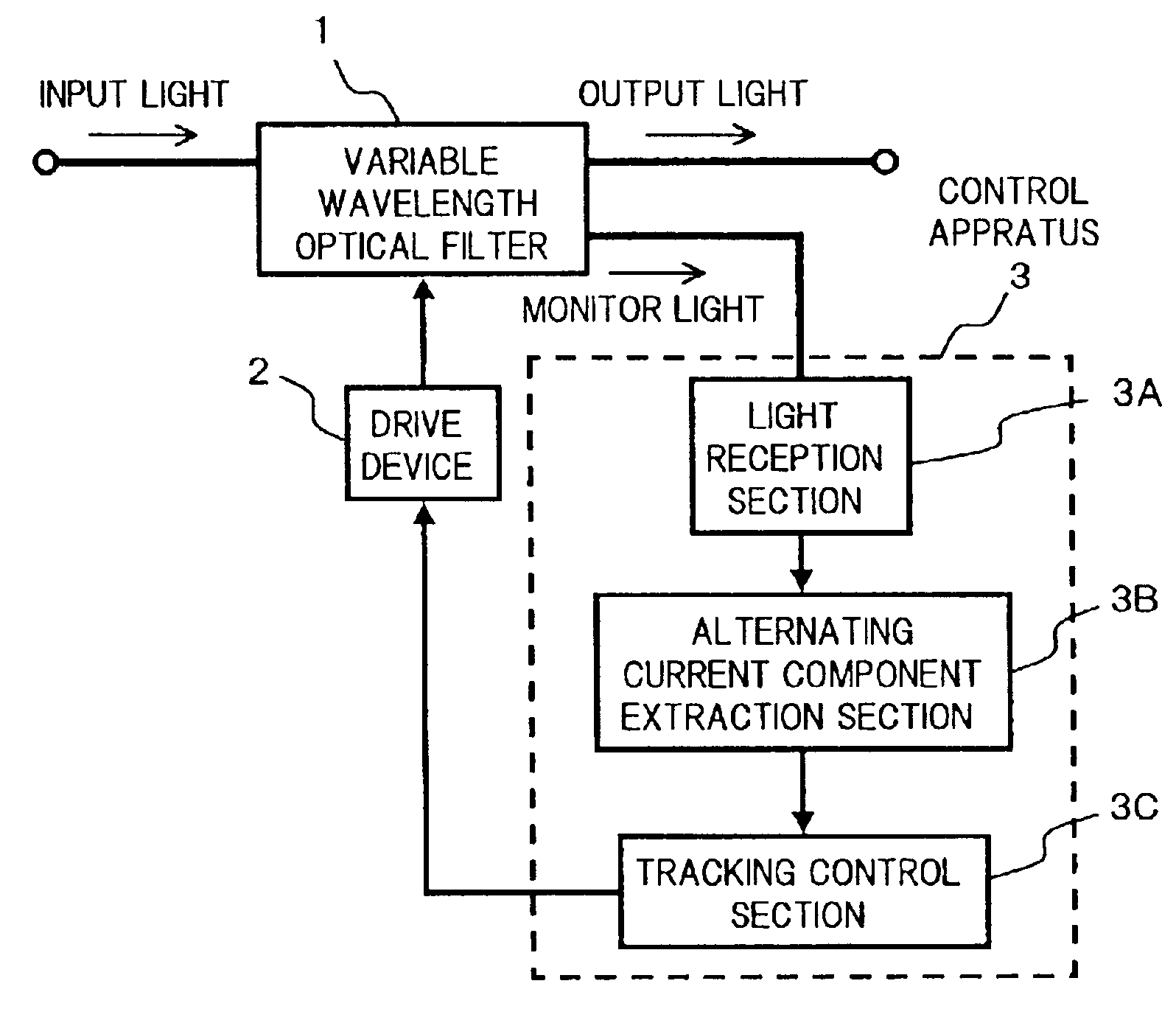
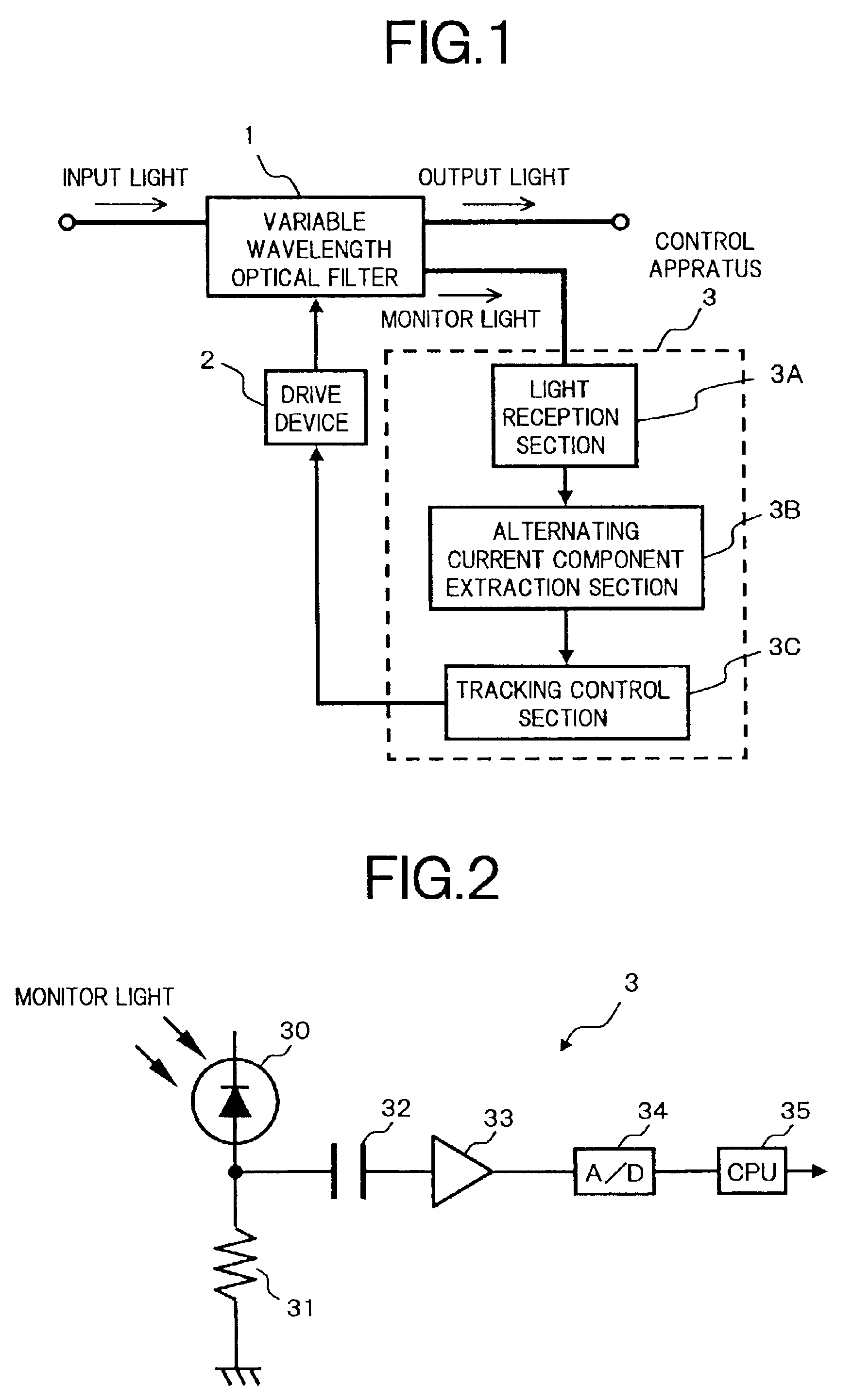
[0051]FIG. 1 is a block diagram showing a control apparatus for a variable wavelength optical filter according to the present invention.

[0052]In FIG. 1, a variable wavelength optical filter 1 which is a device capable of selectively separating in collective, optical signals of desired multiple wavelengths from WDM signal light, can variably set wavelengths of optical signals to be collectively processed, in response to a drive signal from a drive device 2. A control apparatus 3 that tracking controls wavelength setting of the variable wavelength optical filter 1, includes, for example, a light reception section 3A, an alternating current component extraction section 3B and a tracking control section 3C.

[0053]The light reception section 3A receives monitor light taken out from the variable wavelength optical filter 1 and generates an electrical signal corresponding to total power thereof. The alternating current component extraction section 3B extracts an alternating current componen...

second embodiment

[0067]Next is a description of the control apparatus of the variable wavelength optical filter according to the present invention.

[0068]FIG. 5 is a circuit diagram showing a specific configuration example of the control apparatus of the second embodiment.

[0069]In FIG. 5, the configuration of a control apparatus 3a of the present embodiment is different from the configuration of the aforementioned control apparatus 3 shown in the FIG. 2, in that a low pass filter (LPF) 36 is inserted between the output terminal of the amplifier 33 and the input terminal of the A / D converter 34. The components other than the above are the same as for the case of the first embodiment.

[0070]The low pass filter 36 is a typical high frequency cut-off filter cutting off components of frequencies equal to or higher than a preset frequency, for an input signal. This low pass filter 36 is provided, for example, in the case where there is an optical power variation or an output variation in an optical amplifie...

third embodiment

[0074]As follows is a description of the control apparatus for the variable wavelength optical filter according to the present invention.

[0075]FIG. 8 is a circuit diagram showing a specific configuration example of the control apparatus of the third embodiment.

[0076]In FIG. 8, a control apparatus 3b of the present embodiment is constituted such that, for example in the configuration of the aforementioned second embodiment (FIG. 5), an absolute value of the power of the received monitor light is detected, so that the detection result can be utilized in the tracking control. More specifically, there is added a circuit configuration in which the voltage signal is dropped to be received by the A / D converter 34 through an amplifier 33DC and a low pass filter (LPF) 36DC, before taking out the alternating current component by the capacitor 32 from the voltage signal generated by receiving monitor light by the light receiver 30, that is, an input terminal of the amplifier 33DC is connected ...


PUM

PropertyMeasurementUnit
frequencyaaaaaaaaaa
frequencyaaaaaaaaaa
voltageaaaaaaaaaa

Abstract

The present invention has an object to provide a control method and a control apparatus for a variable wavelength optical filter, which can reliably and stably control drive conditions of the variable wavelength optical filter, independent of the number of wavelengths to be selectively separated in collective. To this end, the control apparatus for a variable wavelength optical filter according to the present invention comprises: a light reception section that takes out to receive, in collective, monitor light corresponding to each optical signal selectively separated by the variable wavelength optical filter, and creates a monitor signal a level of which is changed corresponding to the power of the received monitor light; an alternating current component extraction section that extracts an alternating current component of the monitor signal generated by the light reception section; and a tracking control section that controls the drive condition of the variable wavelength optical filter based on a level change in the alternating current component extracted by the alternating current component extraction section.

Description

BACKGROUND OF THE INVENTION[0001](1) Field of the Invention[0002]The present invention relates to a control method and a control apparatus for a variable wavelength optical filter that selectively separates optical signals of desired wavelengths from wavelength division multiplexed (WDM) signal light including a plurality of optical signals of different wavelengths. In particular, the present invention relates to a control technique for a variable wavelength optical filter for when collectively processing selective separation of optical signals of multiple wavelengths.[0003](2) Description of the Related Art[0004]Recently, with the explosive increase in data communication demand mainly on Internet traffic, higher capacity and ultra-longer distances for backbone networks are being demanded. Furthermore, since services used by users are becoming multifarious, there is a demarid to simultaneously realize an economical network having high reliability and flexibility.[0005]Currently, by ...

Claims


Application Information

Patent Timeline
Patent Type & Authority Patents(United States)
IPC IPC(8): G02F1/01G02B6/12G02B6/34G02B5/18H04B10/07H04B10/27H04B10/29H04B10/291H04J14/02
CPCG02B6/12007G02B6/29395G02F1/0121H04J14/0204H04J14/0205H04J14/021H04J14/0213G02F2203/585
Inventor KAI, YUTAKAMIYATA, HIDEYUKITSUYAMA, ISAO
Owner FUJITSU LTD
Why Eureka
Try Eureka