
Boiler for use in a steam generating device

A steam boiler, steam technology, applied in the direction of steam generation, steam generation method, lighting and heating equipment, etc., can solve the problems of not being able to freely choose the position of holes, steam interruption, etc., to improve reliability and durability, reduce heat The effect of the shock effect

Inactive Publication Date: 2007-12-05
KONINKLIJKE PHILIPS ELECTRONICS NV
View PDF1 Cites 5 Cited by
  • Summary
  • Abstract
  • Description
  • Claims
  • Application Information

AI Technical Summary

Problems solved by technology

[0007] The disadvantage of the steam generating device known from EP0821096 is that the water inlet hole needs to be placed in the region of the top area of ​​the bottom of the boiler, and thus the position of the hole cannot be chosen freely
For example, the holes cannot be positioned such as to provide a passage for water to flow into the lower area of ​​the bottom of the boiler, because in this case the lesser amount of heated water present in this lower area would immediately and freshly The supply of cold water mixes, which causes an interruption of steam production

Method used


Image

  • Boiler for use in a steam generating device
  • Boiler for use in a steam generating device
  • Boiler for use in a steam generating device

Examples


Embodiment Construction

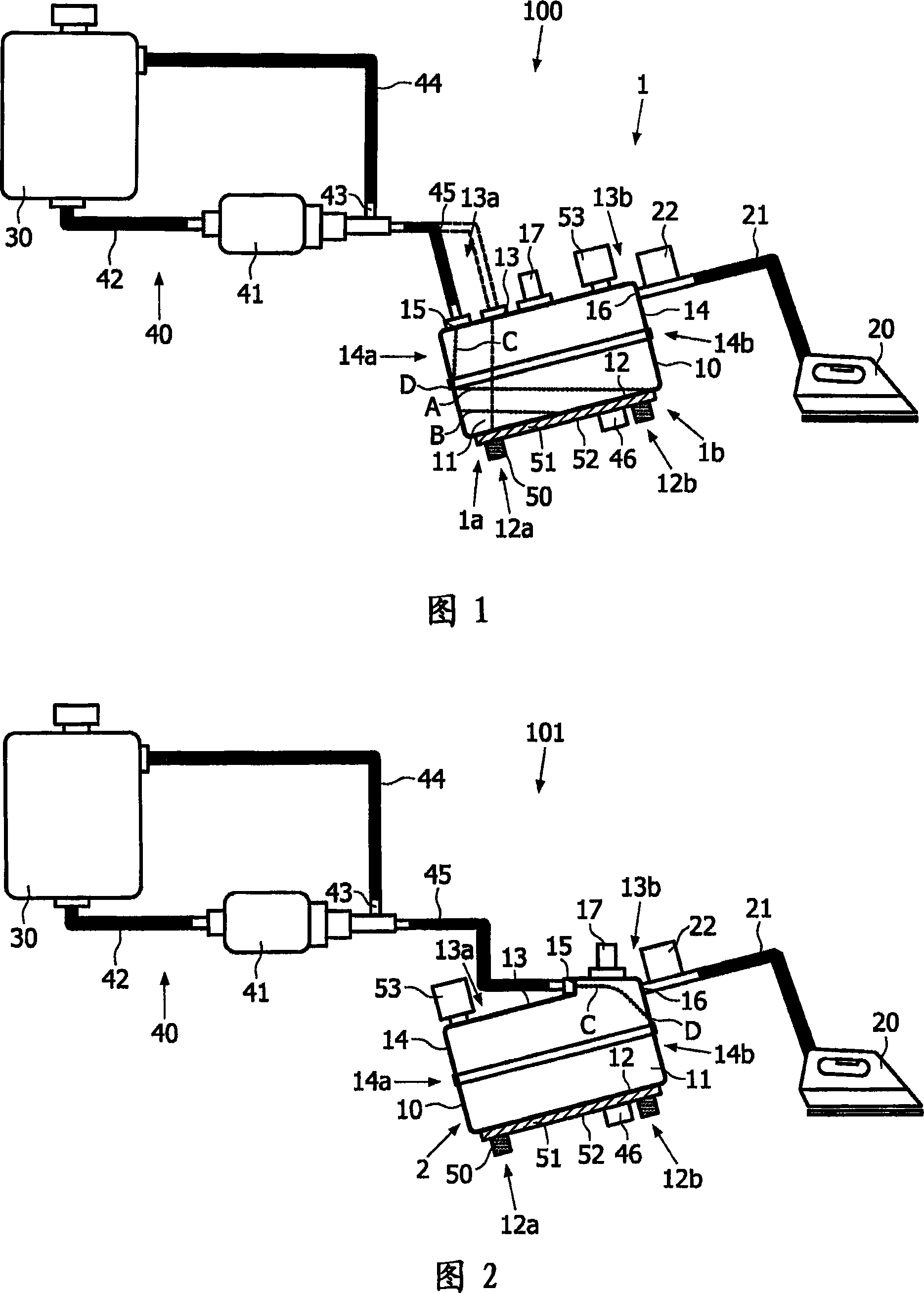
[0030] Fig. 1 schematically shows a steam ironing device 100, comprising a steam boiler 1 according to a first preferred embodiment of the present invention, which is also referred to as a first steam boiler 1 hereinafter. The main function of boiler 1 is to heat water into steam. Typically, the boiler 1 is mounted in a plastic housing (not shown).

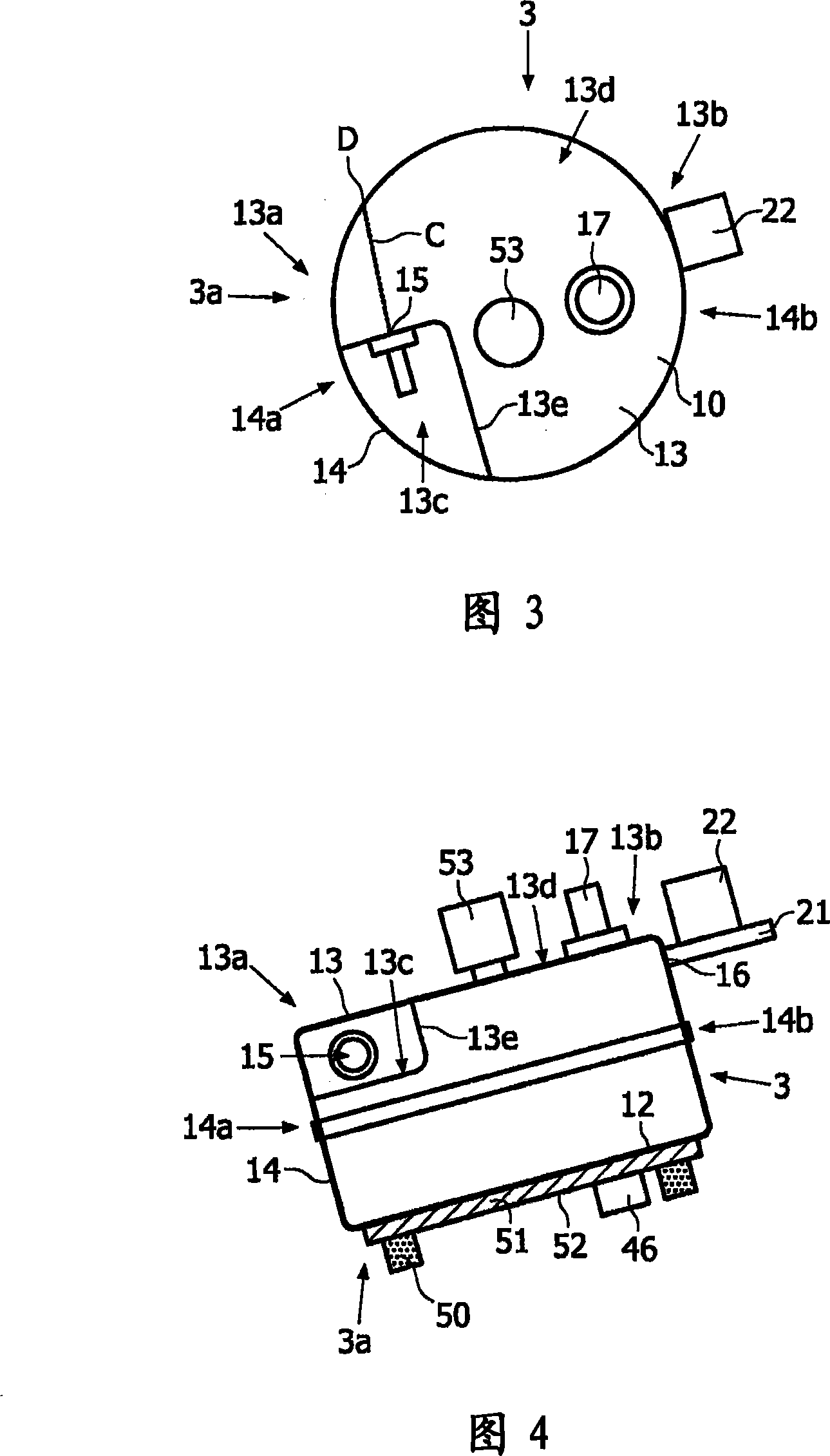
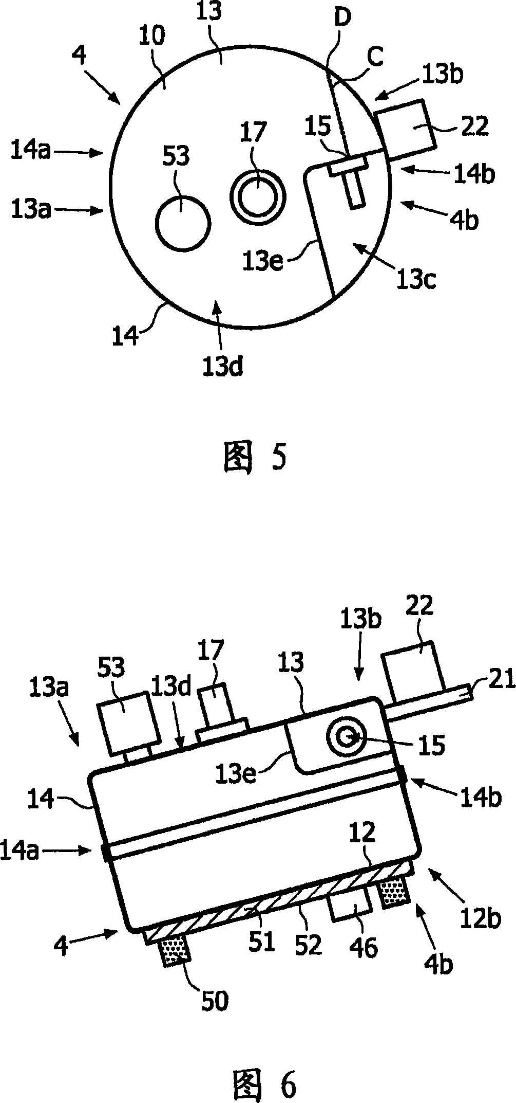
[0031] The boiler 1 comprises a boiler housing 10 enclosing a boiler space 11 in which the process of converting water into steam takes place during operation of the boiler 1 . The boiler housing 10 is preferably made of stainless steel and is shaped like a cylinder including a bottom wall 12 and a top wall 13 . In the example shown, both the bottom wall 12 and the top wall 13 comprise planar sheets. Furthermore, the boiler housing 10 comprises an annular wall 14 extending between the bottom wall 12 and the top wall 13 . In the preferred embodiment of the boiler 1, the annular wall 14 has a circular shape, but this does not cha...


PUM


Abstract

A boiler (1) for heating water to steam comprises a boiler housing (10) having a bottom wall (12), a top wall (13) and a circumferential wall (14) extending between these walls (12, 13). When the boiler (1) is mounted in a steam generating device for generating steam and supplying steam to an appliance such as a steam iron (20), the boiler (1) is given an inclined orientation. In a lower portion (13a) of the top wall (13) of the boiler housing (10), an inlet opening (15) for letting in water to a boiler space (11) which is enclosed by the boiler housing (10) is arranged. When water is supplied through the inlet opening (15), the water lands on a lower zone (14a) of the circumferential wall (14) and flows further in a downward direction, along the circumferential wall (14). As a result, the water is pre-heated when it reaches the water which is already present in the boiler space (11), and there is no danger of the steam production getting interrupted.

Description

technical field [0001] The invention relates to a boiler for heating water, comprising a boiler shell enclosing a boiler space, wherein a water inlet for letting water into the boiler space is arranged in the boiler shell. Background technique [0002] Such steam boilers are well known and used in a variety of personal appliances including steam ironing appliances, active ironing boards capable of supplying steam to the object to be ironed, facial saunas, steam cleaning appliances and coffee makers. [0003] In EP0821096 a steam generating device is disclosed which comprises a boiler, a water tank and a water supply pipe connecting the tank to the boiler, and which has a delivery pump embedded in it. The boiler has a sloping bottom on which a heating plate is mounted externally. In a specific embodiment, the heating plate and the bottom are tightly fitted by bolting, and a thermally conductive paste is applied between them. [0004] For the purpose of controlling the water...

Claims


Application Information

Patent Timeline
Patent Type & Authority Applications(China)
IPC IPC(8): F22B1/28D06F75/12
CPCD06F75/12F22B1/285
Inventor P·C·奎B·E·K·泰T·蒂拉马茨希赛·桑卡拉林加姆A·P·辛格
Owner KONINKLIJKE PHILIPS ELECTRONICS NV
Learn More