Sc cut crystal microbalance

A microbalance and quartz technology, which is applied in the direction of material analysis, measuring device, and instrument using sonic/ultrasonic/infrasonic waves, can solve the problems of detection sensitivity and accuracy deterioration, and no mention of SC-cut quartz oscillator sensor section, etc., and achieve improvement. The effect of correctness

Inactive Publication Date: 2006-07-12
TOYO TSUSHINKI
View PDF3 Cites 6 Cited by
  • Summary
  • Abstract
  • Description
  • Claims
  • Application Information

AI Technical Summary

Problems solved by technology

However, there are problems as follows: For example, when a quartz microbalance is used as a film thickness monitor of a vapor deposition device, the temperature of the AT-cut quartz vibrator as a sensor increases due to the adhesion of the vapor deposition substance, and the frequency change due to temperature and the The superimposition of changes caused by the deposition of vapor deposition substances, coupled with frequency fluctuations due to thermal shock, degrades the accuracy of detection sensitivity
In Japanese Patent Application Laid-Open No. 5-243892, a crystal oscillator is disclosed that uses the B-mode of the SC-cut crystal vibrator as a temperature sensor to compensate the frequency of the C-mode of the main vibration, but does not mention the use of the SC-cut crystal vibrator. Sensor section for SC-cut quartz microbalances
In addition, Japanese Patent Laid-Open No. 2004-304766 discloses the possibility of using SC-cut crystal vibrators for piezoelectric vibrators, but there is the following problem: except for replacing AT-cut crystal vibrators with SC-cut crystal vibrators, there is no specific disclosure on how to use SC-cut crystal vibrators. constitute

Method used


Image

  • Sc cut crystal microbalance
  • Sc cut crystal microbalance
  • Sc cut crystal microbalance

Examples


Embodiment Construction

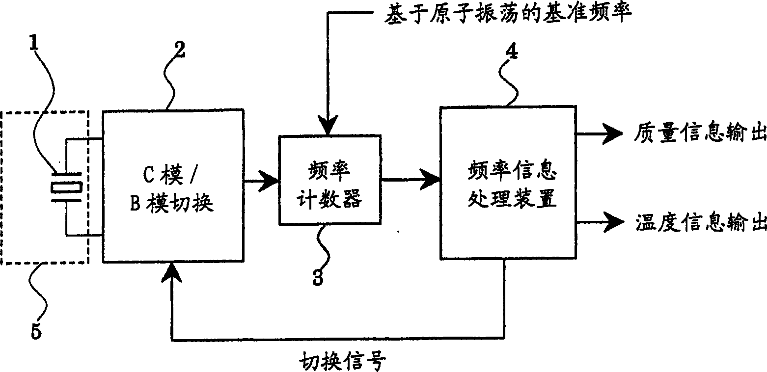
[0036] figure 1It is a circuit block diagram showing an embodiment of the SC-cut quartz microbalance of the present invention, and is composed of an SC-cut quartz vibrator 1 , a C-mode / B-mode switching oscillation circuit 2 , a frequency counter 3 , and a frequency information processing device 4 . The SC-cut quartz vibrator 1 is formed by grinding a quartz substrate cut by rotating about 22 degrees around the Z axis and then about 34 degrees around the X axis to a predetermined thickness, and attaching electrode films on both main surfaces. It is constructed by fixing to the holder with conductive adhesive or welding. The electrode portion of the SC-cut crystal vibrator 1 is placed in the atmosphere 5 to be measured, and the lead wires extending from the two electrode films are connected to the oscillation circuit 2 . The oscillation circuit 2 has a built-in switch that can be controlled by a control signal from the outside, and by switching the switch, the SC-cut crystal r...


PUM


Abstract

A SC cut crystal microbalance includes a SC cut crystal oscillator, a C mode / B mode switching-type oscillation circuit, a frequency countermand a frequency information processing device, wherein the C mode / B mode switching-type oscillation circuit is switched by a signal received from the frequency information processing device, the frequencies of C mode and B mode is measured respectively, variations by temperature change are compensated from frequency variations of C mode based upon temperature information by the frequency change of B mode, and whereby mass change is measured.

Description

technical field [0001] The invention relates to a quartz microbalance, in particular to an improved quartz microbalance capable of compensating for frequency changes caused by temperature, thereby measuring adhesion mass with high precision. Background technique [0002] A quartz microbalance (quartz oscillator microbalance, QCM) that detects a minute mass by utilizing a frequency change of a quartz oscillator is used in various fields. When a mass change Δm (g) occurs on the electrode film of a quartz oscillator, such as an AT-cut quartz oscillator due to a uniform film that is very thin relative to the thickness of the quartz substrate, the change ΔF (Hz) of the resonance frequency of the quartz oscillator is as known That would be represented as follows: [0003] ΔF=-Fo 2 Δm / (K·ρ·A) (1) [0004] Among them, Fo represents the resonant frequency, K represents the frequency constant, ρ represents the density of quartz, and A represents the electrode area. Acco...

Claims


Application Information

Patent Timeline
Patent Type & Authority Applications(China)
IPC IPC(8): H03B5/04H03B5/30H03B5/32
CPCG01N2291/0256G01N29/036
Inventor 佐藤富雄
Owner TOYO TSUSHINKI
Why Eureka
Try Eureka