Diaphragms for combustion chamber pressure sensors

A technology of sensors and combustion chambers, applied in the direction of combustion ignition, combustion methods, measuring fluid pressure, etc.

Inactive Publication Date: 2017-02-22
ROBERT BOSCH GMBH
View PDF8 Cites 0 Cited by
  • Summary
  • Abstract
  • Description
  • Claims
  • Application Information

AI Technical Summary

Problems solved by technology

This at least partially compensates for thermally-induced length changes of the membrane, which are caused, for example, by hot fuel gas and which periodically influence the pressure measurement by means of the pressure sensor.

Method used


Image

  • Diaphragms for combustion chamber pressure sensors
  • Diaphragms for combustion chamber pressure sensors
  • Diaphragms for combustion chamber pressure sensors

Examples


Embodiment Construction

[0016] figure 1 with 2 The sensor membrane according to the prior art is shown.

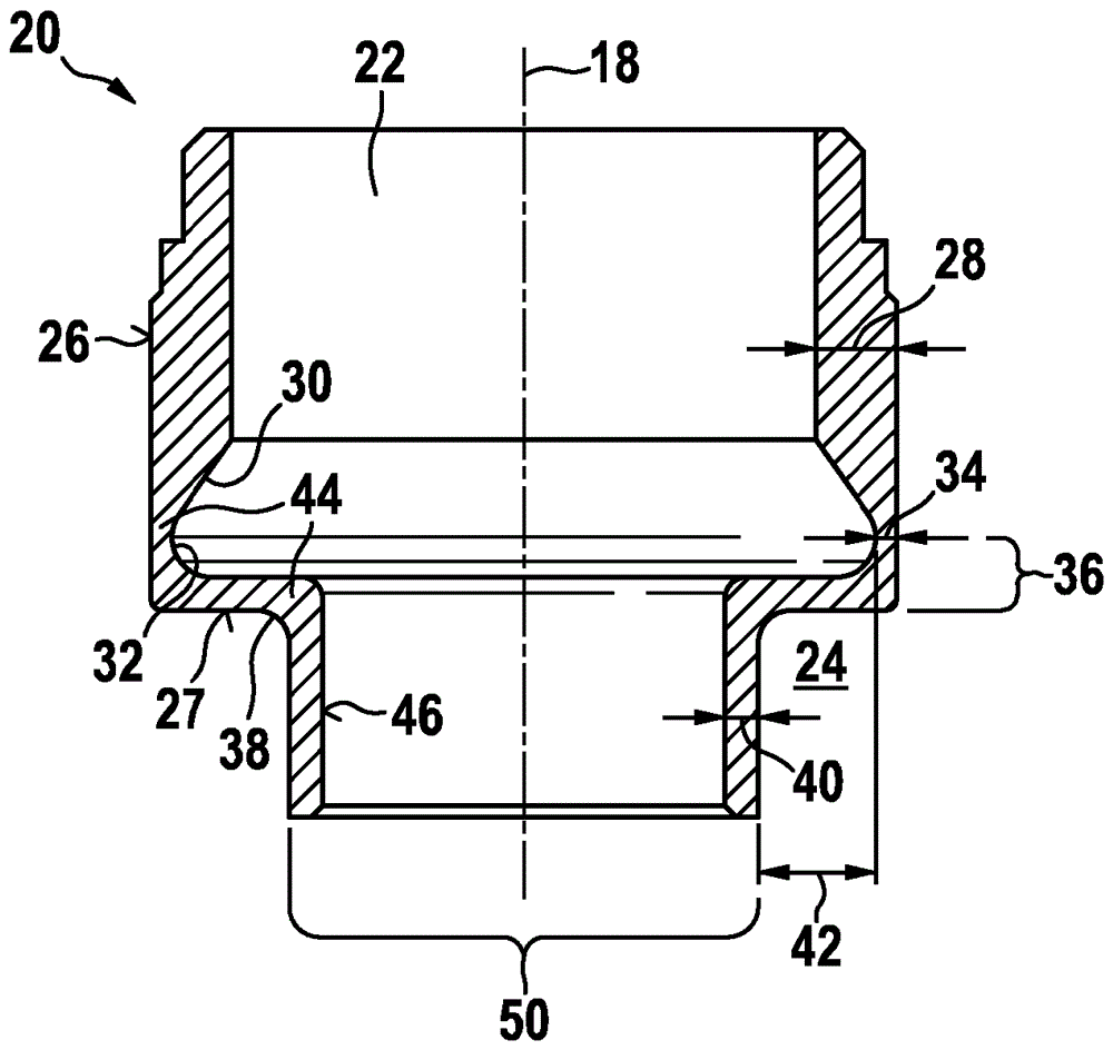
[0017] From figure 1 with 2 It can be seen that the sensor diaphragm 19 is symmetrically configured with respect to its symmetry axis 18 and has a diaphragm cover 26. From figure 2 It can be seen from the cross-sectional view that the sensor diaphragm 19 according to the prior art is constructed with a first wall thickness 28.

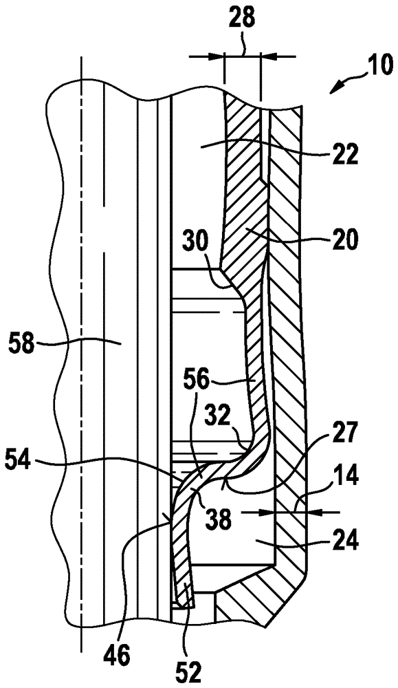
[0018] image 3 A longitudinal section of an embodiment of the combustion chamber pressure sensor according to the invention is shown. The combustion chamber pressure sensor includes a housing 10 in which a pressure rod 58 facing the pressure chamber 24 is accommodated. The pressure rod 58 receives the pressure from the pressure chamber 24 and converts the effect of the pressure into a movement along the axis 18. A cavity 22 is formed between the pressing rod 58 and the housing 10. Furthermore, a measuring sensor mechanism 59 is arranged along the axis 18 behind the pressu...


PUM

PropertyMeasurementUnit
lengthaaaaaaaaaa
thicknessaaaaaaaaaa

Abstract

The invention relates to a pressure measurement device for an internal combustion engine, particularly for determining a combustion chamber pressure. The pressure measurement device comprises a housing (10) in which a sensor membrane (19, 20) is accommodated. Said sensor membrane separates a pressure space (24) from an empty space (22). The sensor membrane (19, 20) comprises a pressurised area (27) and seals off the housing (10) against the pressure to be measured. The pressurised area (27) of the sensor membrane (20) lies between a first deflection point (32) and a second deflection point (38) of the sensor membrane (20), each designed in reduced second and third wall thicknesses (34, 40) relative to a first wall thickness (28) of the sensor membrane.

Description

Background technique [0001] DE 10 2006 057 627 A1 relates to a pressure measuring device. The pressure measuring device is intended to be arranged in the combustion chamber of an internal combustion engine. The pressure measuring device has a housing, a force transmission element, and a pressure sensor, and the force transmission element partially protrudes from the housing at an opening on the chamber side of the housing. The pressure sensor is arranged in the inner cavity of the housing. Here, the pressure sensor is in operative connection with the force transmission element. In addition, a diaphragm is provided, which seals the inner cavity of the housing in which the pressure sensor is arranged with respect to the opening on the chamber side. The diaphragm, which is preferably configured as a metal diaphragm, has a force transmission element which is oriented in the axial direction of the force transmission element. Furthermore, the pressure sensor is in operative connec...

Claims


Application Information

Patent Timeline
Patent Type & Authority Patents(China)
IPC IPC(8): G01L19/06G01L23/10G01L23/22F23Q7/00
CPCG01L19/0627F23Q7/001F23Q2007/005G01L23/10G01L23/22
Inventor H.肖尔岑R.弗拉维格尼W.克茨勒J.沃尔夫A.普罗布斯特
Owner ROBERT BOSCH GMBH
Why Eureka
Try Eureka