Microbe limit filter

A microbial limit and filter technology, applied in enzymology/microbiology devices, biochemical instruments, methods of supporting/immobilizing microorganisms, etc., can solve problems such as inability to take out, pollute filter membranes, and inaccurate microbial detection, and achieve membrane removal Easy, avoid microbial contamination, ensure the effect of accuracy

Active Publication Date: 2007-12-12
ZHEJIANG TAILIN BIOENG
View PDF1 Cites 4 Cited by
  • Summary
  • Abstract
  • Description
  • Claims
  • Application Information

AI Technical Summary

Problems solved by technology

[0002] Chinese patent application ZL200720105905.0 relates to a microbial limit tester. The filter disclosed in it is fixedly installed on the casing of the tester. The pipeline is equipped with a deflation solenoid valve that can eliminate the negative pressure in the system pipeline. When the filter cup is to be removed after filtration, the negative pressure in the suction channel must be released first. Since the deflation solenoid valve is set in the system casing On the pipeline, and the system pipeline in the casing cannot be taken out for sterilization. When the solenoid valve deflates to release the negative pressure in the suction channel, the microorganisms in the pipeline will directly pollute the filter membrane through the flow of gas, resulting in Inaccurate microbiological testing

Method used


Image

  • Microbe limit filter

Examples


Embodiment 1

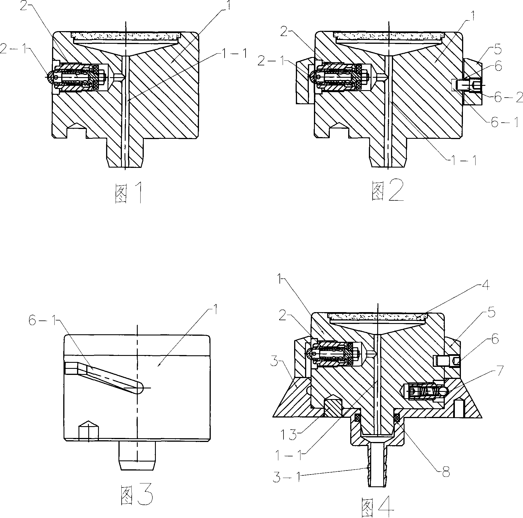
[0013] As shown in Figure 1, the microbial limit filter described in this embodiment includes a filter head 1, on which an air release valve 2 is provided, and the air release switch 2-1 of the air release valve 2 is set in the filter In the side direction of the head 1, the other end of the air release valve 2 communicates with the air suction channel 1-1.

Embodiment 2

[0015] As shown in Figure 2, the microbial limit filter described in this embodiment is provided with a cup taker 5 outside the filter head 1, and a rotating upward structure 6 is provided between the cup taker 5 and the filter head 1 to deflate The vent switch 2-1 of the valve 2 opens and closes by touching and separating with the inner wall of the cup remover 5. The rotating upward structure 6 between the cup taker 5 and the filter head 1 is shown in FIG. 3, and a chute 6-1 is provided on one side of the cylindrical surface between the cup taker 5 and the filter head 1. , The other side is provided with a groove 6-2 at the corresponding chute 6-1. The said groove and tenon 6-2 can be pins, screws, marbles and the like. Here, the chute 6-1 is provided on the cylindrical surface of the filter head 1, and the cup remover 5 is provided with a groove 6-2. The groove 6-2 is a screw and inserted into the chute 6-1.

Embodiment 3

[0017] As shown in Figure 4, the microbial limit filter described in this embodiment is provided with a support 3 under the filter head 1, and a slot-type release positioning structure 7 is provided between the filter head 1 and the support 3, and the support 3 The bottom is provided with a suction nozzle 3-1 communicating with the suction channel 1-1, a positioning hole pin 13 is provided between the bottom of the filter head 1 and the support 3, and a positioning hole pin 13 is provided between the filter head 1 and the support 3 There is a sealing ring 8 and a filter sheet 4 is arranged on the filter surface of the filter head. When in use, the filter head 1 can be easily removed from the support 3 or inserted.


PUM


Abstract

The invention relates to a microbiological filter, comprising filtering head, gas discharge valve, discharge switch is installed on side part of filtering head, the other end of discharge valve is connected with suction channel, the filter head is equipped with cup taking device, a rotary upgoing structure is equipped between cup taking device and filtering head, the open and close of gas discharge switch is controlled through contact and separation with inner wall of cup taking device, the lower part of filter is provided with support stand, one channel- section discharging fixation structure is installed between filtering head and support stand, the bottom of support stand is equipped with suction nozzle connected with suction channel. The invention is characterized in that the filtering head is detachable, and can be cleaned and disinfected, which avoids bacteria infection, and there is no bacteria infection for filtering membrane, which guarantees good process for experiment and test accuracy.

Description

Technical field [0001] The invention relates to a microbial limit filter for detecting microorganisms. Background technique [0002] Chinese patent application ZL200720105905.0 relates to a microbial limit tester. The disclosed filter is fixedly installed on the housing of the tester. The suction channel in the filter is connected with the system pipeline in the housing. The pipeline is equipped with a deflation solenoid valve that can eliminate the negative pressure in the system pipeline. When the filter cup is to be removed after filtration, the negative pressure in the suction channel must be released first, because the deflation solenoid valve is installed in the system housing On the pipeline, and the system pipeline in the casing cannot be taken out for sterilization. When the solenoid valve is vented to release the negative pressure in the suction channel, the microorganisms in the pipeline will directly contaminate the filter membrane through the circulation of gas, resu...

Claims


Application Information

Patent Timeline
Patent Type & Authority Applications(China)
IPC IPC(8): C12M1/12C12M1/34
Inventor 叶大林
Owner ZHEJIANG TAILIN BIOENG
Why Eureka
Try Eureka