Heating cooking instrument

A technology of cooker and halogen heater, applied in the field of electric heating cooker

Inactive Publication Date: 2012-02-29
HITACHI APPLIANCES INC
View PDF10 Cites 0 Cited by
  • Summary
  • Abstract
  • Description
  • Claims
  • Application Information

AI Technical Summary

Problems solved by technology

[0031] In addition, as shown in Patent Document 4, in the case of a heating and cooking device using a far-infrared ray generating mechanism that radiates 2.5 to 3 μm of far-infrared rays at the center, there is almost no It emits visible light below 0.8μm, so it is difficult to use as a lighting mechanism

Method used


Image

  • Heating cooking instrument
  • Heating cooking instrument
  • Heating cooking instrument

Examples


Embodiment 1

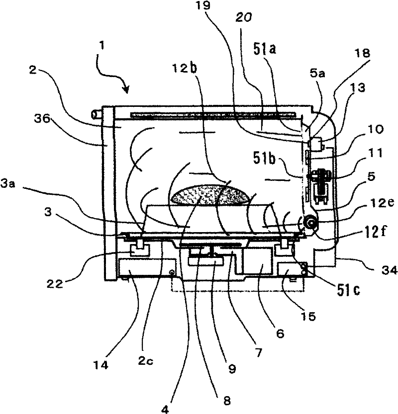
[0083] refer to Figure 1 to Figure 3 A heating cooker as a first embodiment of the present invention will be described.

[0084] figure 1 It is a side sectional view of a state in which an object to be heated 4 is heated by an electric microwave oven as a heating cooker of the present invention.

[0085] figure 2 It is a front view of the interior of the heating chamber seen from the front side with the door of the microwave oven opened.

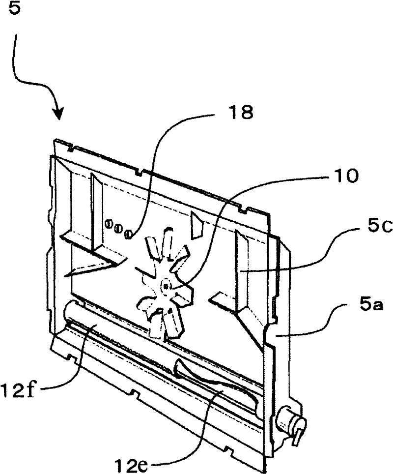
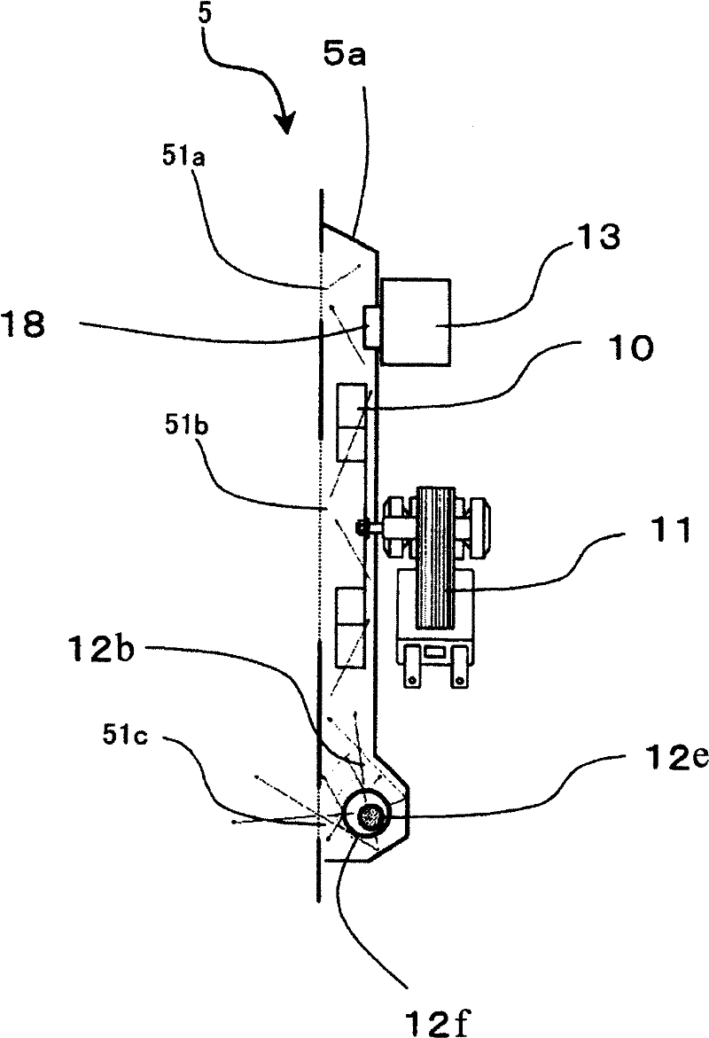
[0086] image 3 It is a perspective view of the hot air unit of the microwave oven.

[0087] The main body 1 of microwave oven is made up of following each part: frame body 35 that constitutes outer contour; Be arranged in frame body 35 and receive the heating chamber 2 of the heated object 4 such as the food that will heat cook; Be arranged on this heating chamber 2 The worktable 3 below and placing the object to be heated 4; the hot air unit 5 that circulates high-temperature air in the heating chamber 2; the magnetron 6 that gener...

Embodiment 2

[0140] refer to Image 6 as well as Figure 7 A heating cooker according to a second embodiment of the present invention will be described.

[0141] Image 6 is a side sectional view of the microwave oven according to the present embodiment.

[0142] This embodiment is characterized in that a halogen heater 12h that radiates a near-infrared wavelength of 0.8 to 2.0 μm at the center is provided as illumination that also functions as an illumination means and a heating means.

[0143] Figure 7 is a graph showing the relationship between the wavelength and the irradiance of the halogen heater 12h according to the present embodiment.

[0144] Here, the irradiance is a parameter indicating the light intensity of a specific wavelength included in the radiated light, and is represented by energy per unit area.

[0145] That is, in the halogen heater 12h according to the present embodiment, as Figure 7 As shown, the illuminance has a peak in the near-infrared region with a wav...

Embodiment 3

[0163] refer to Figure 8 A third embodiment according to the present invention will be described.

[0164] Figure 8 It is a heating cooker that is equipped with a steam generating mechanism 13 on the back upper side of the hot air unit 5 and can perform heating cooking in which steam is supplied to the heating chamber 2 .

[0165] According to this embodiment, not only the saturated water vapor generated by the steam generating mechanism 13 is directly supplied to the heating chamber 2, but also the saturated water vapor particles generated by the steam generating mechanism 13 can be crushed and refined by the blower mechanism 10, and then heated with halogen. The device 12h is further overheated so that superheated steam of 100 to 300° C. can be generated in the hot air unit 5 and supplied to the heating chamber 2 .

[0166] Thereby, compared with the case where heating cooking is performed using only the hot air supplied from the upper heater 38 and the hot air unit 5 wi...


PUM


Abstract

The invention relates to a heat cooking device, easy to observe the status of heating the things during cooking from the front of the heat cooking device body. The use convenience is increased at the same time the atmosphere of heating cooking is increased like cooking using charcoal fire. The heat cooking device provided with a heat chamber characterized by comprising the following which is provided in a case and stores a heated thing, and space provided between said cases at the back side of a backboard of this heat chamber. Two or more holes provided in said backboard. A light source whichemits visible light with a wavelength of 0.4-0.8 micrometer provided in a position which is in said space and illuminates the bottom of a heat chamber via two or more holes. A reflective means to be in said space, and to be arranged up, and to turn catoptric light of light from this light source to a front face of said heat chamber, and to irradiate with it via said hole from this light source.

Description

technical field [0001] The invention relates to an electric heating cooker. Background technique [0002] Conventionally, in such a heating cooker, in order to facilitate observation of a heating state of an object to be heated housed in the heating chamber, an illuminating mechanism for illuminating the heating chamber is provided. [0003] Generally, the lighting mechanism is arranged outside the side of the heating chamber, and holes for passing light and shielding electromagnetic waves are provided on the wall of the heating chamber where the lighting mechanism is arranged. [0004] Here, as the lighting mechanism, a small lamp with a power consumption of 10 to 30 W is often used as the box lamp, and the box lamp is arranged on the upper side of the heating chamber, and irradiates light from above the object to be heated placed in the heating chamber. [0005] Therefore, the brightness of the heating chamber is brightest on the side closer to the interior light, and gra...

Claims


Application Information

Patent Timeline
Patent Type & Authority Patents(China)
IPC IPC(8): F24C7/06F24C15/00
CPCY02B40/143Y02B40/00
Inventor 田中佐知本间满木村秀行小泽圣长谷川雄一立川晃之伊丹启光大都纪之
Owner HITACHI APPLIANCES INC
Why Eureka
Try Eureka