Matrix multiplier device based on single FPGA

A technology of matrix multiplier and matrix multiplication, applied in the field of FPGA technology and high-performance computing

Inactive Publication Date: 2007-12-12
ZHEJIANG UNIV
View PDF0 Cites 14 Cited by
  • Summary
  • Abstract
  • Description
  • Claims
  • Application Information

AI Technical Summary

Problems solved by technology

[0005] At present, there have been some achievements in the use of FPGA to realize matrix multiplication calculations, but they can only be used to complete one of dense matrix multiplication, sparse ma

Method used


Image

  • Matrix multiplier device based on single FPGA
  • Matrix multiplier device based on single FPGA

Examples


Embodiment Construction

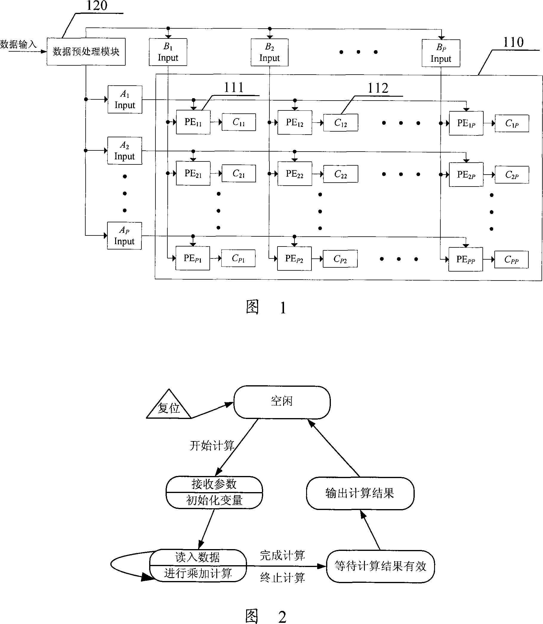
[0025] As shown in Figure 1, a matrix multiplier device based on a single FPGA specifically includes:

[0026] Realize P in a single FPGA chip by using FPGA internal DSP unit 2 A calculation unit PE (Processing Element) 111, which is used to perform multiplication and addition calculation operations on input data;

[0027] Each calculation unit PE 111 is configured with a storage unit 112 for storing calculation results;

[0028] Will P 2 A computing unit PE111 is arranged as a P×P PE array 110 for matrix multiplication calculation;

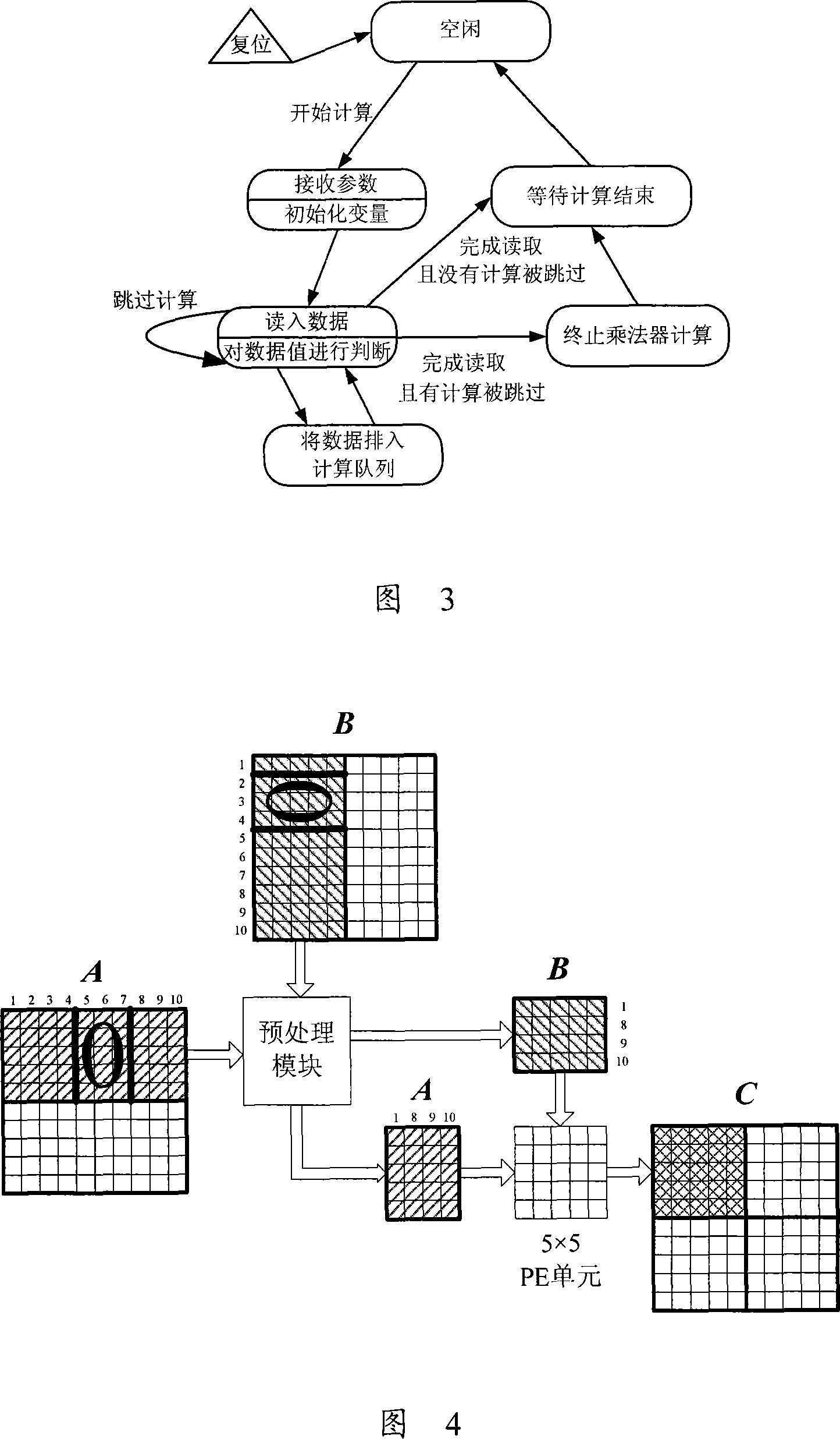
[0029] A data preprocessing module 120 is configured in front of the PE array 110 to analyze the values ​​of the input matrix elements, so as to prevent the 0-element blocks in the sparse matrix from participating in the multiplication and addition calculation.

[0030] The working process of the PE array 110 is shown in Figure 2. After reset, the multiplier is in an idle state. After receiving the "start calculation" command, the multiplier i...


PUM


Abstract

The invention relates to a single FPGA matrix multiplication device that comprises P2 PEs formed in P row and P column matrix, data input and output interface and data pre processing unit. It can manage dense matrix and loose matrix multiplication with improvement in computing performance. It also relates to a matrix multiplication device based on FPGA.

Description

technical field [0001] The invention relates to the field of FPGA technology and high-performance computing technology, in particular to an FPGA-based matrix multiplier device. Background technique [0002] Matrix multiplication operation is a basic operation in scientific computing, widely exists in process control, image processing, digital signal processing and other fields, and is usually the most time-consuming key operation in the calculation process. The time complexity of matrix multiplication calculation is high, usually O(N 3 ), its computing performance directly affects the overall performance of the system. [0003] The previous matrix multiplier is usually implemented by a general-purpose processor or a digital signal processor (DigitalSignal Processor, DSP). General-purpose processors and DSPs have the advantages of relatively mature technology, complete implementation tools, and simple programming. However, due to the limitations of their internal structures...

Claims


Application Information

Patent Timeline
IPC IPC(8): G06F7/52
Inventor 陈耀武田翔
Owner ZHEJIANG UNIV
Why Eureka
Try Eureka