Enhanced Time-Interleaved A/D Conversion Using Compression

a compression and time-interleave technology, applied in the field of compression, can solve the problems of storing sampled data in semiconductor memory or on disks, unable to keep up, and creating bottlenecks and large memory requirements, so as to achieve a higher compression ratio and reduce the quality of the decompressed stream created during lossy compression

Inactive Publication Date: 2008-01-24
ALTERA CORP
View PDF14 Cites 49 Cited by
  • Summary
  • Abstract
  • Description
  • Claims
  • Application Information

AI Technical Summary

Benefits of technology

[0023]Another object of the invention is to incorporate both lossless and lossy compression. In lossless compression, the sampled data stream recovered after decompressing the compressed samples is identical to the original sampled data stream. In lossy compression, the sampled data stream recovered after decompressing the compressed samples approximates the original sampled data stream. While the signal quality of the decompressed stream create...

Problems solved by technology

Data transfers, especially over legacy interfaces, may not be able to keep up with data output from the TIADC, thus creating bottlenecks and large memory requirements.
As data converter technology improves and sample rate and bit width per sample increase, the problems of transferring sampled data streams over standard busses or networks and storing sampled data in semiconductor memory or on disks become worse.
These problems are made N times more difficult when the sampled data are generated by N parallel time interleaved ADCs.
Since the maximum sample rate of the fastest single A/D converters (flash A/D converters) is limited to about 1 Gsamp/sec, the oscilloscope sample rates required to measure such wideband signals can only be achieved using TIADCs.
Furthermore, the oscilloscope sample capture memory must be designed to accept the higher-rate samples, and that is not always easily achieved.
For example, the fastest available memory technolog...

Method used


Image

  • Enhanced Time-Interleaved A/D Conversion Using Compression
  • Enhanced Time-Interleaved A/D Conversion Using Compression
  • Enhanced Time-Interleaved A/D Conversion Using Compression

Examples


Embodiment Construction

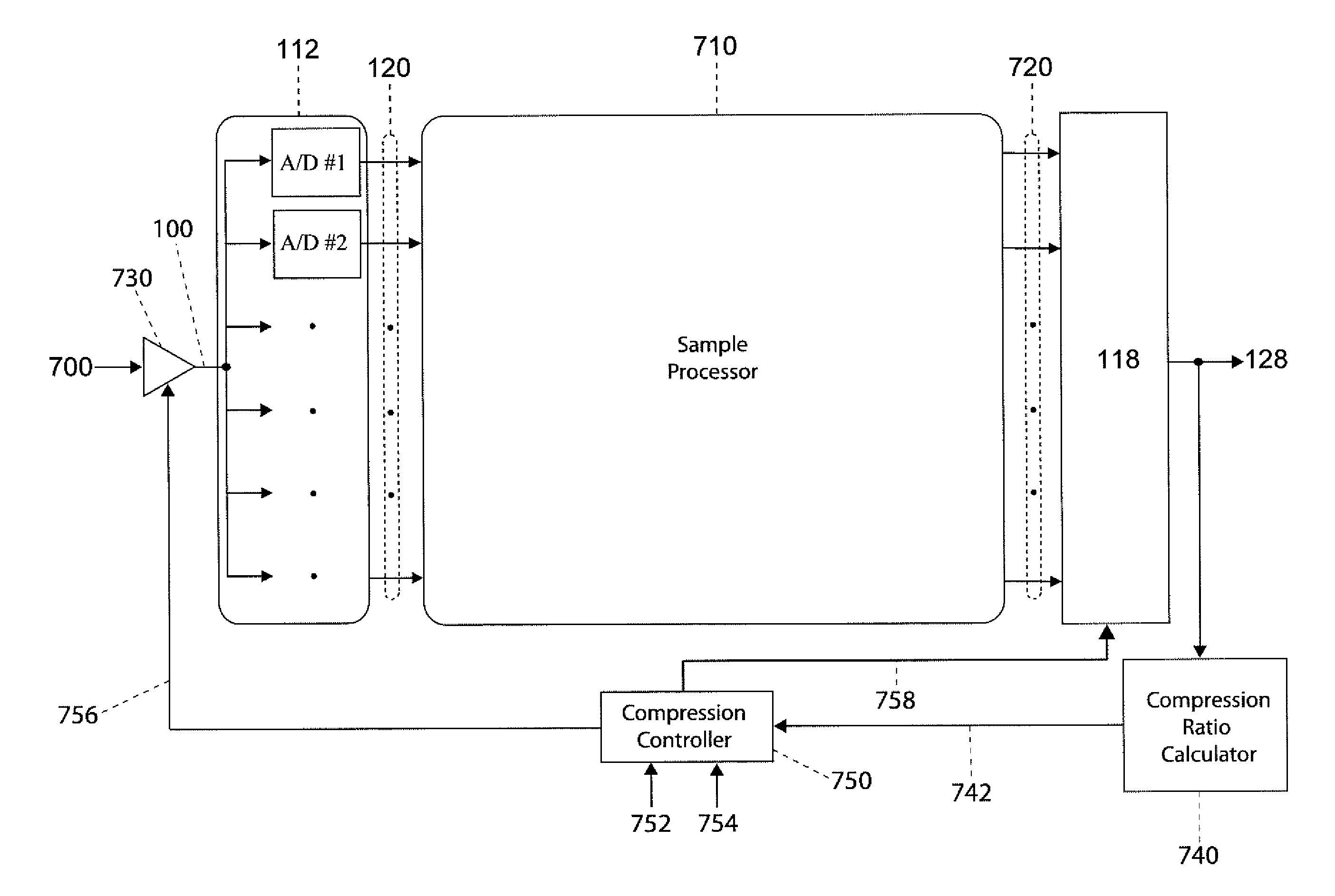
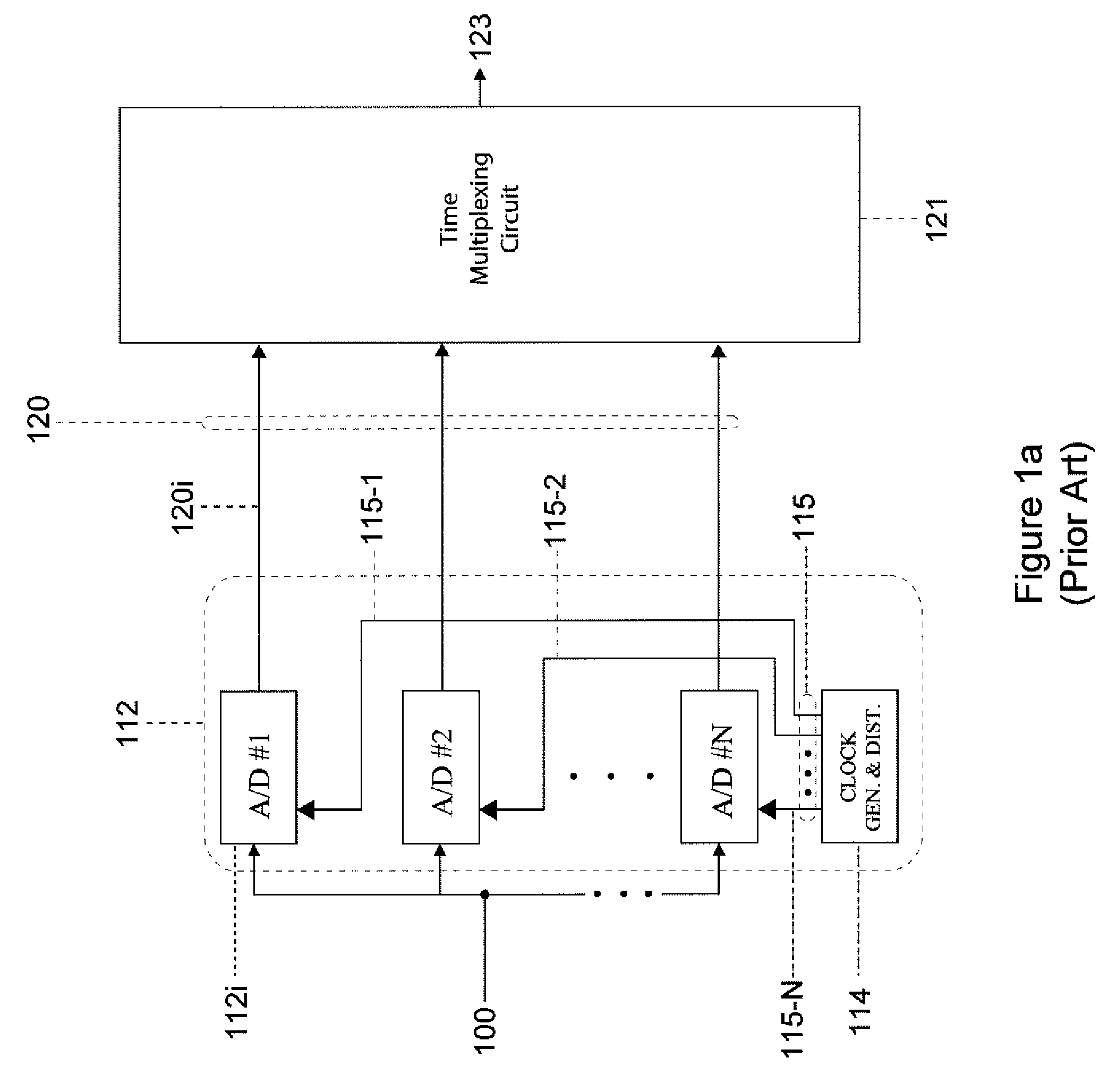
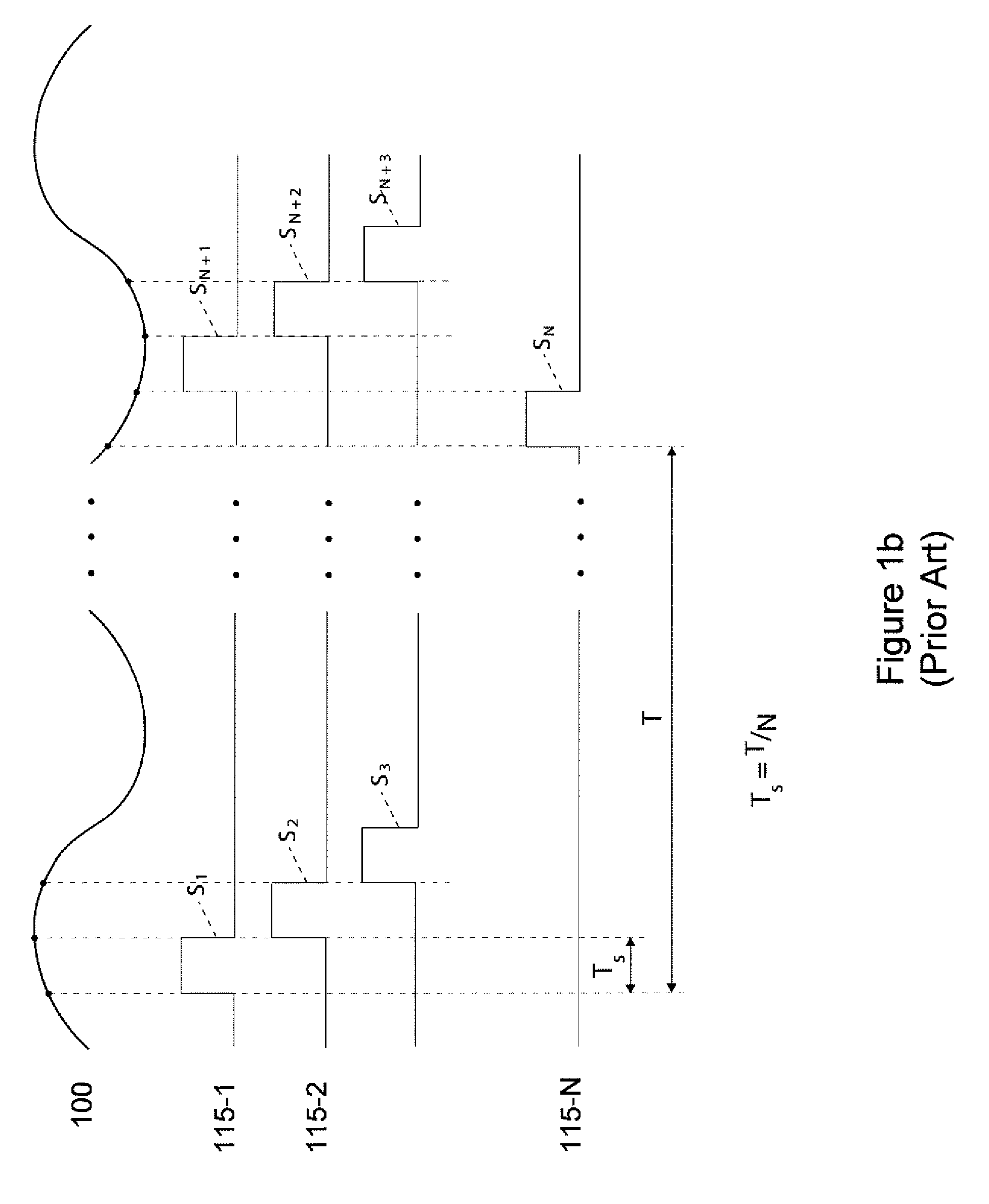
[0036]The present invention compresses signal samples output from a TIADC. A block diagram of a conventional TIADC familiar to those skilled in the art is given in FIG. 1a. The TIADC of FIG. 1a is designed to achieve a sample rate fs that is N times as great as the sample rate fsADC of an individual ADC by using N parallel ADCs, where N is at least 2. Clock generator and distributor 114 provides timing control signals 115 for activating each of the ADCs 112i at predetermined time intervals. For example, timing control signals 115-1, 115-2 and 115-N are coupled to A / D#1, A / D#2 and A / D#N, respectively. Upon activation by timing control signals 115, each ADC 112i samples an analog signal 100 to produce a signal sample 120i. During a clock interval T, the TIADC produces a plurality of signal samples 120 that are consecutive and separated in time by a predetermined sampling interval Ts. In a conventional TIADC, a time multiplexing circuit 121 selectively receives the plurality of signal ...


PUM


Abstract

Compression of signal samples output from a parallel, time-interleaved analog to digital converter (TIADC) for a baseband signal, includes calculating first or higher order differences of consecutive signal samples followed by lossless or lossy encoding of the difference samples to produce compressed samples. Compression of a TIADC output signal with a nonzero center frequency, includes calculating sums or differences of pairs of signal samples separated by an appropriate number of sampling intervals followed by lossless or lossy encoding. The sums or differences of the signal samples have lower magnitudes than the original samples, allowing more efficient compression. Lossy compression alternatives produce compressed data with a fixed bit rate or with a fixed quality in the decompressed samples. Alternatives for lossy compression include attenuating the analog signal before sampling by the TIADC, applying bit shifters or multipliers after sampling to reduce the magnitudes of the signal samples, and lossy encoding.

Description

CROSS-REFERENCE TO OTHER APPLICATIONS[0001]None.FEDERALLY SPONSORED RESEARCH OR DEVELOPMENT[0002]None.PARTIES TO A JOINT RESEARCH AGREEMENT[0003]None.BACKGROUND OF THE INVENTION[0004]The present invention relates to the compression of signal samples generated by parallel, time-interleaved analog to digital (A / D) converters and to the subsequent decompression of the compressed samples.[0005]Parallel, time-interleaved analog to digital converters (TIADCs) are well known by those skilled the art as being useful for high speed data conversion of analog signals. TIADCs are used to sample analog signals at high sample rates, usually above 100 Msamp / sec. A TIADC can sample an analog signal at a sample rate fs that is a multiple of the sample rate fsADC of a single analog to digital converter (ADC). In general, a TIADC device includes two or more individual analog to digital converters operating in parallel at the same sample rate, with each ADC sampling at a different phase offset. The res...

Claims


Application Information

Patent Timeline
IPC IPC(8): H03M7/00
CPCH03M7/30H03M1/1215
Inventor WEGENER, ALBERT W.
Owner ALTERA CORP
Why Eureka
Try Eureka