Manufacturing method for upper groove chamber of split vacuum groove chamber of vacuum refining device

A technology of vacuum refining and manufacturing method, applied in the field of vacuum refining devices, can solve the problems of high processing cost and low processing efficiency, and achieve the effects of high processing efficiency, improving processing efficiency and reducing processing difficulty

Inactive Publication Date: 2007-12-19
BAOSTEEL ENG & TECH GRP
View PDF0 Cites 0 Cited by
  • Summary
  • Abstract
  • Description
  • Claims
  • Application Information

AI Technical Summary

Problems solved by technology

[0006] The task of the present invention is to provide an improved method for manufacturing the upper chamber of the split vacuum chamber of the vacuum refining device, which solves the problems of low processing efficiency and high processing cost in the traditional manufacturing of vacuum chambers

Method used


Image

  • Manufacturing method for upper groove chamber of split vacuum groove chamber of vacuum refining device

Examples


Embodiment Construction

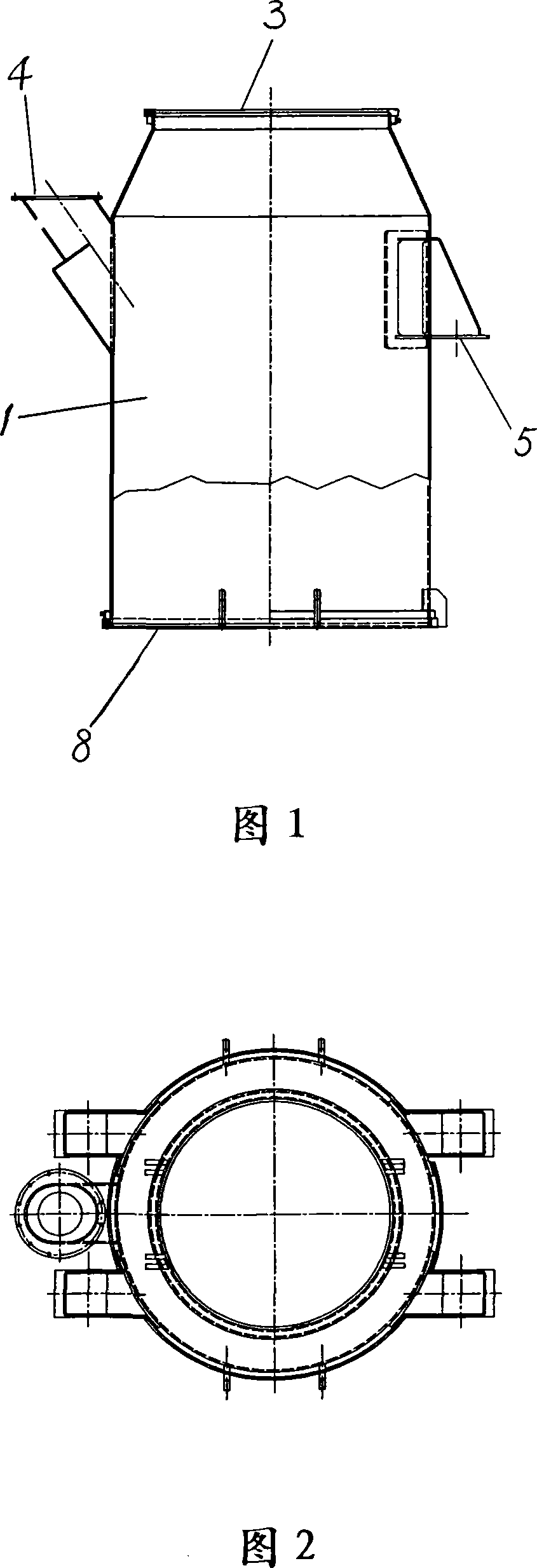
[0020] Referring to the upper tank chamber of the split-type vacuum chamber of the vacuum refining device of Fig. 1 and Fig. 2, the upper tank chamber of the split-type vacuum chamber of the vacuum refining device is manufactured according to the manufacturing method of the present invention, and processed according to the following steps , taking the 300-ton RH vacuum refining unit as an example:

[0021] 1. Divide the upper vacuum chamber 1 of the split type vacuum chamber into upper and lower sections for manufacture, and the joints of the two sections adopt full penetration butt welding joints, and conduct 100% ultrasonic or radiographic testing. The height from the upper flange to the bottom is in the range of 3000-3400mm as the upper section, and the height of the rest is taken as the lower section. The height of the upper section of the split-type vacuum chamber from the top flange 3 to the bottom is in the range of 3000-3400mm, and the upper section includes the top fl...


PUM


Abstract

This invented upper vacuum chamber of splitted vacuum chamber of vacuum refinery installation is manufactured from two parts, which upper part is 3,000mm-3,400mm height from top opening flange, containing top opening flange, sealing ditch, feed opening flange and seat for vacuum chamber; and the rest is the lower part of the invented chamber. The two parts are respectively manufactured, annealed, processed by large scale vertical lathe. After that, the manufacted two parts are full fusion welded together, proceeding local annealing, processed by large scale ordinary floor type borer, finally proceeded 100% ultrasonic test or rays test.

Description

technical field [0001] The invention relates to a vacuum refining device in the metallurgical manufacturing industry, in particular to a method for manufacturing an upper tank chamber of a split vacuum tank chamber in a vacuum refining device adopting a vacuum circulation degassing method (RH). Background technique [0002] The vacuum tank or vacuum chamber is one of the important equipment in the RH vacuum refining device. When the vacuum tank chamber is processing molten steel, its interior is in a vacuum state, and molten steel circulates in it. When the vacuum chamber does not process molten steel, its interior returns to normal pressure. The internal temperature and pressure of the vacuum chamber fluctuate, the working conditions are harsh, the operating load is high, the reliability of the equipment is high, and the manufacturing quality must be strictly guaranteed. [0003] The main body of the vacuum chamber is welded steel structure, lined with heat insulation and...

Claims


Application Information

Patent Timeline
Patent Type & Authority Applications(China)
IPC IPC(8): C21C7/10B23P15/00
Inventor 刘安
Owner BAOSTEEL ENG & TECH GRP
Why Eureka
Try Eureka