
Method of Machining Impeller by Numerical Control Using Macro Program

A technology of macro program and impeller, which is applied in the field of CNC machining of impeller by using macro program, which can solve the problems of inconvenient program search and modification, difficulty in timely reset, time-consuming transmission, etc., and achieves convenient program search and modification, short debugging preparation time, and improved production efficiency effect

Active Publication Date: 2017-08-01
四川泛华航空仪表电器有限公司
View PDF7 Cites 0 Cited by
  • Summary
  • Abstract
  • Description
  • Claims
  • Application Information

AI Technical Summary

Problems solved by technology

[0003] 1. The program has a large amount of data and time-consuming transmission
[0004] 2. To modify or adjust the tool compensation needs to be output again
[0005] 3. When the breakpoint is caused by a knife or other reasons, it is difficult to reset in time
[0007] The processing of impeller parts usually requires the use of five-axis machine tools and programming software to generate processing programs. The processing programs are often bulky and cumbersome to modify
And the traditional four-axis FANUC machine tool manual programming is the main program combined with subroutines, which needs to write a large number of subroutines separately, call the subroutines in the main program to execute the cycle, the main program and subroutines will form several separate programs, and the program search and modification very inconvenient

Method used


Image

  • Method of Machining Impeller by Numerical Control Using Macro Program
  • Method of Machining Impeller by Numerical Control Using Macro Program
  • Method of Machining Impeller by Numerical Control Using Macro Program

Examples


Embodiment Construction

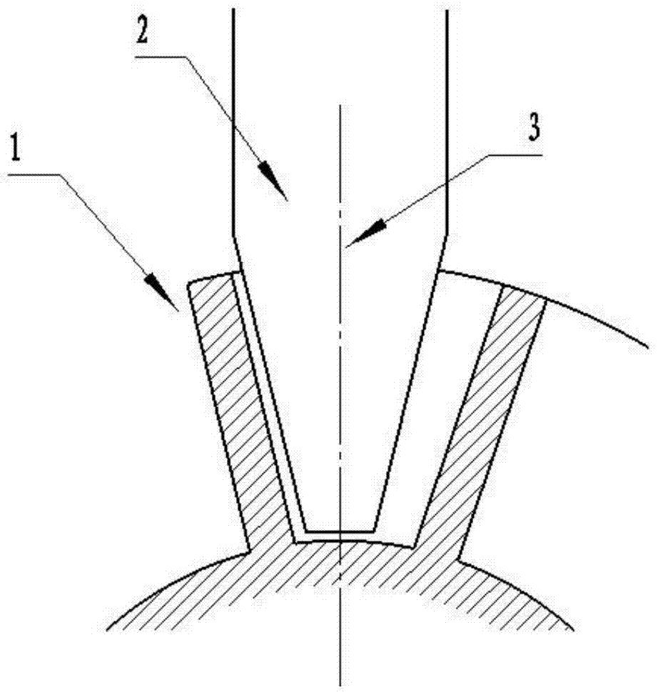
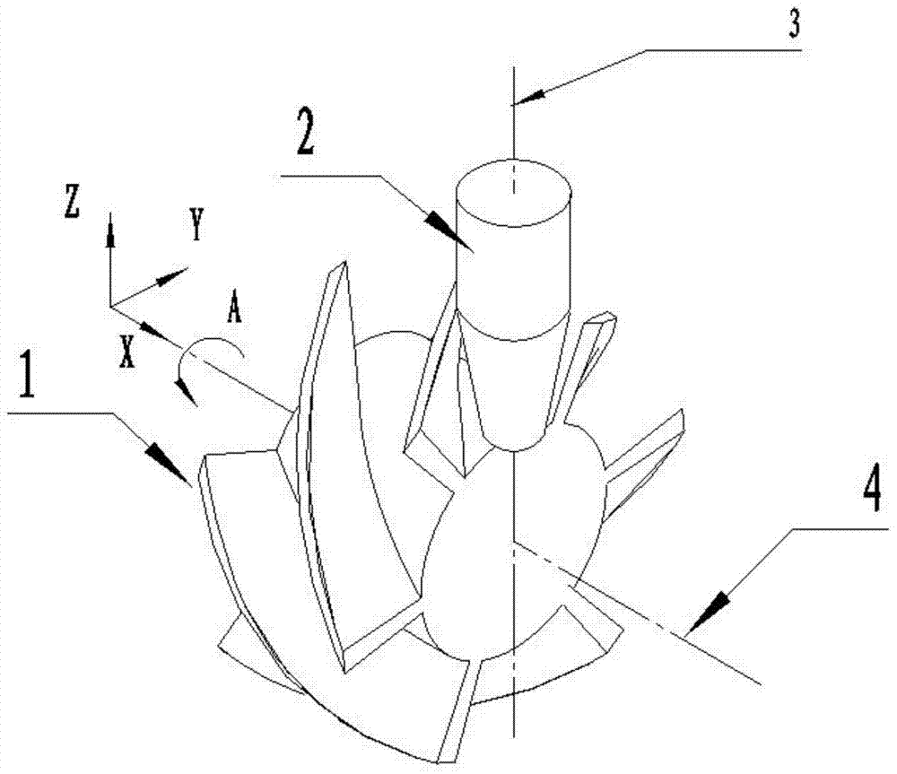
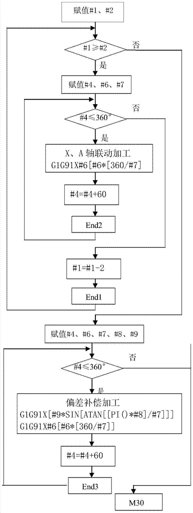
[0019] refer to figure 1 . The impeller part 1 is composed of uniformly distributed blades on the curved surface of the impeller. According to the present invention, the composition characteristics of the blades on the curved surface of the impeller part 1 are analyzed to determine the processing route. In the establishment of the mathematical model and the cycle body, establish the motion trajectory function formula A=[X*[360 / impeller lead]] between the impeller machining rotary axis A and the linear motion axis X; in the macro program compilation, set #1 =18, #1 is the Z-direction assignment of the processing depth; #2=6, #2 is the lowest point of the processing depth; the program nesting between the impeller processing depth and the processing angle is determined by the processing depth condition judgment statement WHILE[#1GE# 2] DO1, and blade processing angle cycle judgment statement WHILE[#4LE360]DO2; use G91 relative value command G1G91X#6A[#6*[360 / #7]]F500 to carry o...


PUM


Abstract

The invention provides a method for numerical control machining of an impeller by utilization of macroprogram and aims to provide the machining method which is short in microprogam debugging preparation time and can improve the machining efficiency of the impeller. By means of the technical scheme, the method comprises the steps that a motion trail functional expression A=[X*[360 / impeller lead]] between an impeller machining rotation shaft A and a linear motion axis X is built; in the microprogram compilation, programs between the impeller machining depth and the machining angle are nested and composed of a machining depth conditional judgment statement WHILE[#1GE#2]DO1 and a blade machining angle loop judgment statement respectively; linkage machining is conducted through a G91 relative value instruction G1G91X#6A[#6*[360 / #7]]F500; fitting milling of a curved face is conducted through a taper machining face of a milling cutter; and an impeller part is fixed to the center of the rotation shaft A of a four-axis machine tool, Y-direction and Z-direction machining original points of the machine tool are arranged in the rotation center of the shaft A, the feed direction is along the rotation axis, and the curved face machining of the impeller is finished through multi-axis linkage.

Description

technical field [0001] The invention relates to a method for processing an impeller on a four-axis numerically controlled milling machine by using a macro program. Background technique [0002] With the rapid development of industrial technology, the shape of products is becoming more and more complex, the requirements for precision are getting higher and higher, and the replacement of products is getting faster and faster. Traditional equipment can no longer meet the new requirements. CNC lathes, CNC milling machines, machining center machines, CNC grinding machines and other CNC machine tools have been widely used in the manufacturing industry. The processing of these advanced equipment needs to be controlled by programs and operated by highly skilled people. To give full play to the high precision, high efficiency and high flexibility of CNC machine tools, operators are required to have excellent programming skills. Commonly used programming methods are manual programmi...

Claims


Application Information

Patent Timeline
Patent Type & Authority Patents(China)
IPC IPC(8): B23C3/18
Inventor 黄杰
Owner 四川泛华航空仪表电器有限公司
Learn More