
A positioning device and laser processing equipment

A positioning device and positioning arm technology, used in metal processing equipment, laser welding equipment, welding equipment and other directions, can solve the problems of glass edge damage, inability to precisely control the clamping force, slow speed, etc., to achieve short replacement time, clamping Constant force, easy to control, fast effect

Active Publication Date: 2019-11-05
南京魔迪多维数码科技有限公司
View PDF5 Cites 0 Cited by
  • Summary
  • Abstract
  • Description
  • Claims
  • Application Information

AI Technical Summary

Problems solved by technology

[0004] The purpose of the present invention is to provide a positioning device to improve the existing positioning equipment that needs to be manually fixed. This method is slow and cannot accurately control the clamping force, and it is easy to cause excessive stress at the contact point between the positioning protrusion and the glass. Problems with broken glass edges
[0005] The purpose of the present invention is to provide a laser processing equipment to improve the existing positioning equipment that needs to be fixed manually. This method is slow and cannot accurately control the clamping force. Problems that cause glass edges to break

Method used


Image

  • A positioning device and laser processing equipment
  • A positioning device and laser processing equipment
  • A positioning device and laser processing equipment

Examples


Embodiment 1

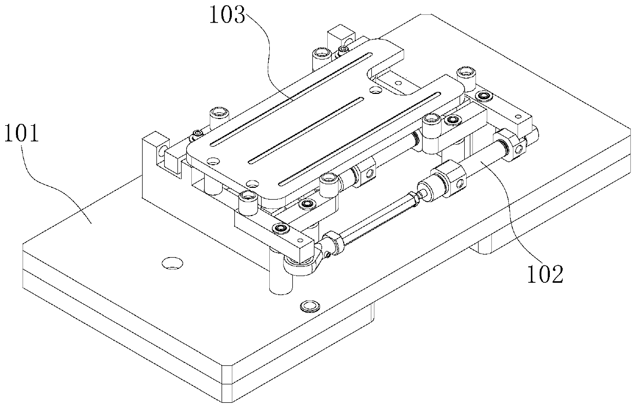
[0043] refer to Figure 1 to Figure 5 , this embodiment provides a positioning device 11, including a support plate 101, a clamping positioning system 102 and a fixing system 103;

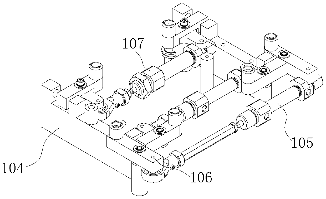
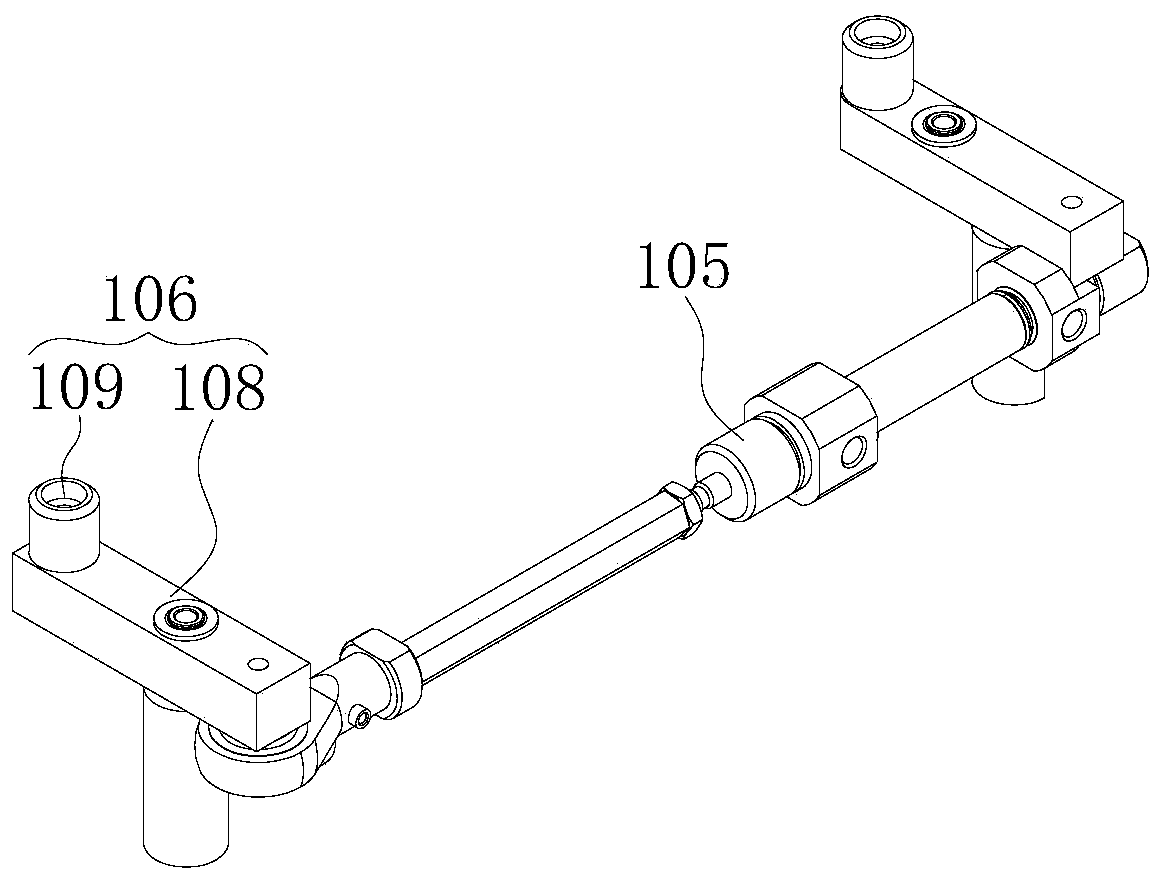
[0044] The clamping positioning system 102 includes a limiting part 104, a first telescopic structure 105, two first clamping parts 106 and two second clamping parts 107, the limiting part 104 is installed on the support plate 101, and the two first clamping parts The tightening part 106 is arranged oppositely, and the two second clamping parts 107 are arranged oppositely, and the connecting line of the two first clamping parts 106 and the connecting line of the two second clamping parts 107 are perpendicular to each other; The two ends are respectively connected with two first clamping parts 106, the second clamping part 107 includes a second telescopic structure 110 and a clamping mechanism, the clamping mechanism is installed on the position limiting part 104, and the second telescopic structure...

Embodiment 2

[0064] refer to Figure 6 , this embodiment also provides a positioning device 11, this embodiment is a further improvement on the basis of the technical solution of embodiment 1, the technical solution described in embodiment 1 is also applicable to this embodiment, embodiment 1 has been disclosed The technical solution is no longer described repeatedly.

[0065] Specifically, the difference between this embodiment and Embodiment 1 is that the positioning device 11 of the positioning device 11 provided by this embodiment includes two clamping positioning systems 102 and two fixing systems 103, two clamping positioning systems 102 and two The two fixing systems 103 are installed on the support plate 101 respectively, the two fixing systems 103 are arranged at intervals, and the two clamping and positioning systems 102 cooperate with the two fixing systems 103 respectively.

[0066] The positioning device 11 provided in this embodiment is provided with two identical devices, w...

Embodiment 3

[0068] This embodiment provides a laser processing device, including a processing device and the above positioning device 11, and the positioning device 11 is located at the output end of the processing device.


PUM


Abstract

The invention provides a positioning device and laser processing equipment, and belongs to the field of laser processing. The positioning device comprises a supporting plate, a clamping positioning system and a fixing system. The clamping positioning system comprises a limiting part, a first telescoping structure, two first clamping parts and two second clamping parts. The connecting line of the two first clamping parts and the connecting line of the two second clamping parts are perpendicular to each other. The two ends of the first telescoping structure are connected with the two first clamping parts separately. The second clamping parts comprise second telescoping structures and clamping mechanisms, and the second telescoping structures are in drive connection with the clamping mechanisms. The fixing system comprises a vacuum generator and an adsorption plate. The vacuum generator is installed on the supporting plate. The positioning device provided by the invention is high in speedand high in precision, clamping force is constant and easy to control, the replacement time of workpieces is lowered to the minimum degree, energy consumption for laser waiting is reduced by matchinghigh-speed processing of lasers, and the processing capacity of laser equipment is given into full play.

Description

technical field [0001] The invention relates to the field of laser processing, in particular to a positioning device and laser processing equipment. Background technique [0002] Glass is a kind of hard and brittle material, which is widely used in screen protection industries such as mobile phones and tablets, and has irreplaceable practical value. Traditional flat glass peripheral cutting and chamfering rely on contact processing with special tools and machine tools. This processing method produces large stress on the glass and low yield. In recent years, with the gradual maturity of laser technology, equipment for non-contact cold processing of glass using ultrashort pulse lasers has gradually entered the market. This type of equipment has the characteristics of good precision, fast efficiency and high yield. The high precision of laser processing puts forward high technical requirements for the positioning and fixing devices of glass plates. Therefore, the development ...

Claims


Application Information

Patent Timeline
Patent Type & Authority Patents(China)
IPC IPC(8): B23K26/70B23K26/38
CPCB23K26/38B23K26/70B23K26/702
Inventor 托马斯·爱德华·尼尔森洪觉慧施瑞温海涛张运芝杨迪陈岩潘红宇
Owner 南京魔迪多维数码科技有限公司
Learn More