Supercharge Your Innovation With Domain-Expert AI Agents!

Condensation water recovery system

A technology for recovering system and condensed water, applied in supplementary water supply, preheating, steam generation, etc., which can solve the problems of energy waste and achieve energy saving, quantifiable control, and stable and reliable operation

Inactive Publication Date: 2007-12-19
QUANZHOU TIANLONG ENVIRONMENTAL ENG
View PDF2 Cites 6 Cited by
  • Summary
  • Abstract
  • Description
  • Claims
  • Application Information

AI Technical Summary

Problems solved by technology

[0004] The purpose of the present invention is to provide a fully enclosed condensate recovery system that saves energy, operates stably and reliably, and can be quantified in order to solve the problem of large energy waste in the existing condensate recovery treatment method

Method used


Image

  • Condensation water recovery system
  • Condensation water recovery system

Examples


Embodiment Construction

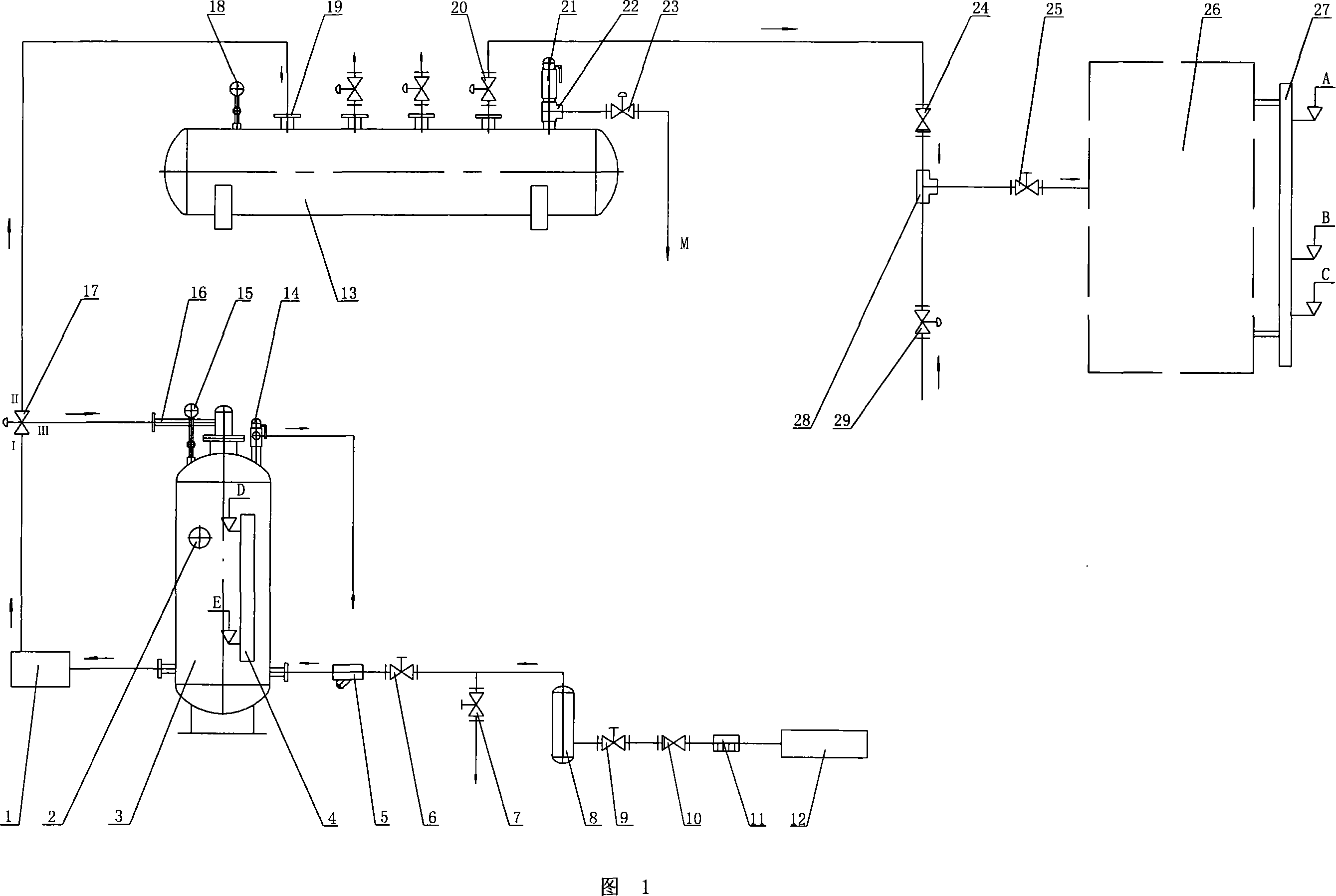
[0012] Referring to Fig. 1, the present invention is provided with multi-stage pump 1, thermometer 2, water storage tank 3, liquid level gauge 4, filter 5, first manual valve 9, third manual valve 7, second manual valve 6, fourth Manual valve 25, buffer 8, first one-way valve 10, second one-way valve 24, steam trap 11, water diversion cylinder 13, safety valves 14 and 21, pressure gauges 15 and 18, return pipe 16, pneumatic tee Valve 17, water inlet flange 19, first pneumatic valve 20, second pneumatic valve 29, third pneumatic valve 23, first three-way pipe 28, second three-way pipe 22 and other corresponding connecting pipes.

[0013] The condensed water outlet of the steam-using equipment 12 is connected to the water inlet of the buffer 8 through the steam trap 11, the first one-way valve 10, and the first manual valve 9. The manual valve 6 and the filter 5 are connected to the lower inlet of the water storage tank 3, and the lower outlet of the water storage tank 3 is conn...


PUM


Abstract

The present invention relates to a condensate water recovery system, belonging to a water treatment equipment. Said condensate water recovery system is formed from the following several portions: water storage tank, multi-stage pump, buffer, pneumatic three-way valve, pneumatic valves, water-dividing cylinder, one-way valves, hand-operated valves and bleeder. Said invention also provides the connection mode of all the above-mentioned portions, and also provides the working principle of said condensate water recovery system and its concrete operation method.

Description

technical field [0001] The invention relates to a water treatment device, in particular to a water treatment system for recovering and recycling condensed water. Background technique [0002] Condensed water exists widely in modern industries, especially in the textile printing and dyeing industry. Due to the extensive use of boilers, condensed water is bound to be produced. Some companies let the condensed water be discharged directly through a steam trap, resulting in a direct waste of energy and water resources; some companies use an open recovery system to recycle the condensed water, that is, let the condensed water flow back to a water collection tank before being reused The disadvantage is that after the condensed water enters the water collection tank, a large amount of secondary flash steam will be generated due to the pressure drop. Due to the existence of latent heat of vaporization, the secondary flash steam carries a large amount of heat energy and is discharged...

Claims


Application Information

Patent Timeline
IPC IPC(8): F22D11/00F22D11/06
Inventor 傅太平
Owner QUANZHOU TIANLONG ENVIRONMENTAL ENG
Features
  • R&D
  • Intellectual Property
  • Life Sciences
  • Materials
  • Tech Scout
  • Unparalleled Data Quality
  • Higher Quality Content
  • 60% Fewer Hallucinations
Learn More