Solenoid valve for controlling the flow of brake oil

A technology of solenoid valve and brake fluid, applied in the field of solenoid valve, can solve the problem of small turning angle of the vehicle

Inactive Publication Date: 2007-12-26
HYUNDAI MOBIS CO LTD
View PDF0 Cites 7 Cited by
  • Summary
  • Abstract
  • Description
  • Claims
  • Application Information

AI Technical Summary

Problems solved by technology

[0008] At the same time, if the contact between the tires and the road surface reaches a limit when the front wheels are turning or if the inner side of the rear wheels is subjected to excessive turning direction stress when turning, understeer phenomenon will occur, that is, the vehicle turns at an angle smaller than the driver's ideal steering angle.

Method used


Image

  • Solenoid valve for controlling the flow of brake oil
  • Solenoid valve for controlling the flow of brake oil
  • Solenoid valve for controlling the flow of brake oil

Examples


Embodiment Construction

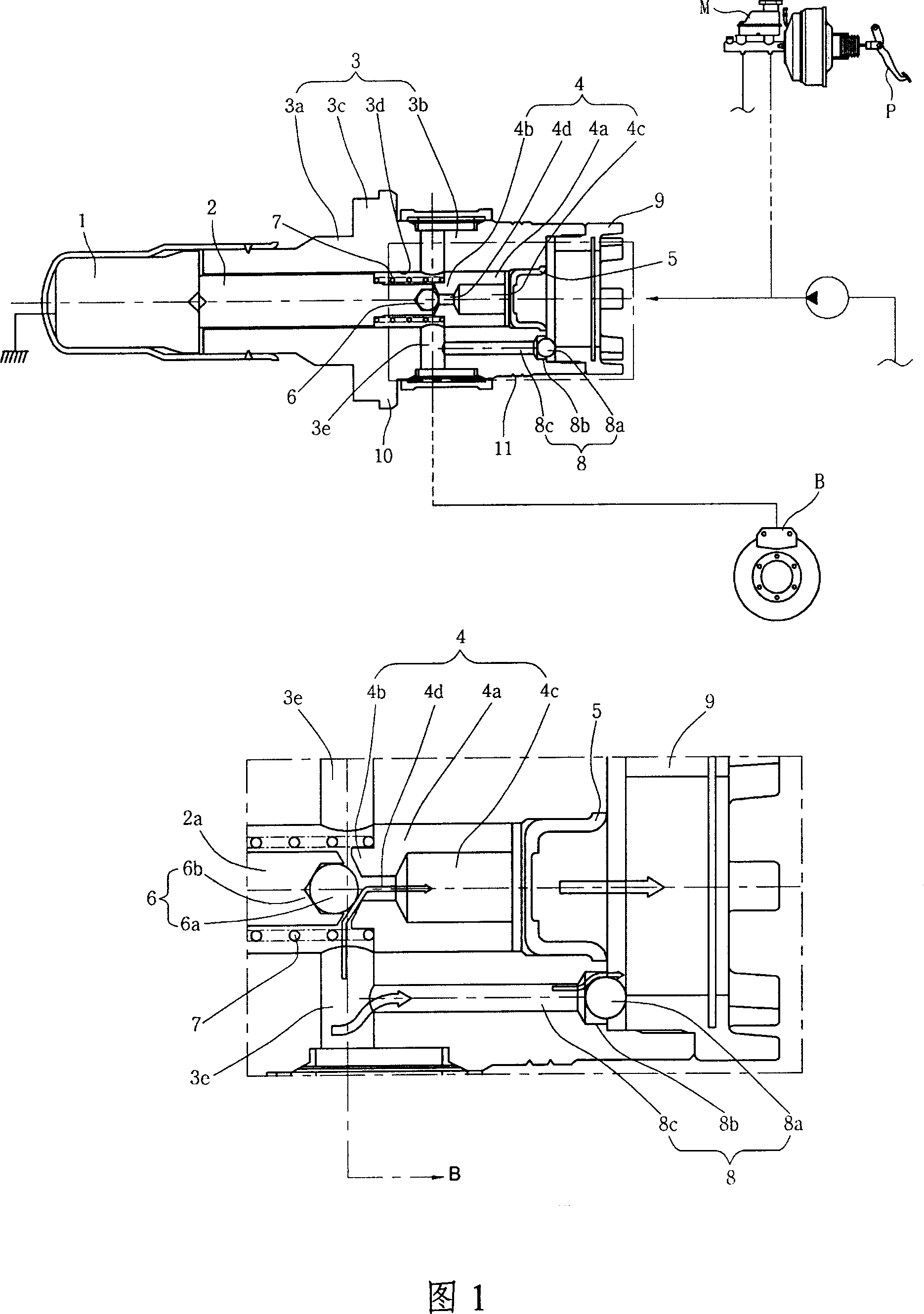
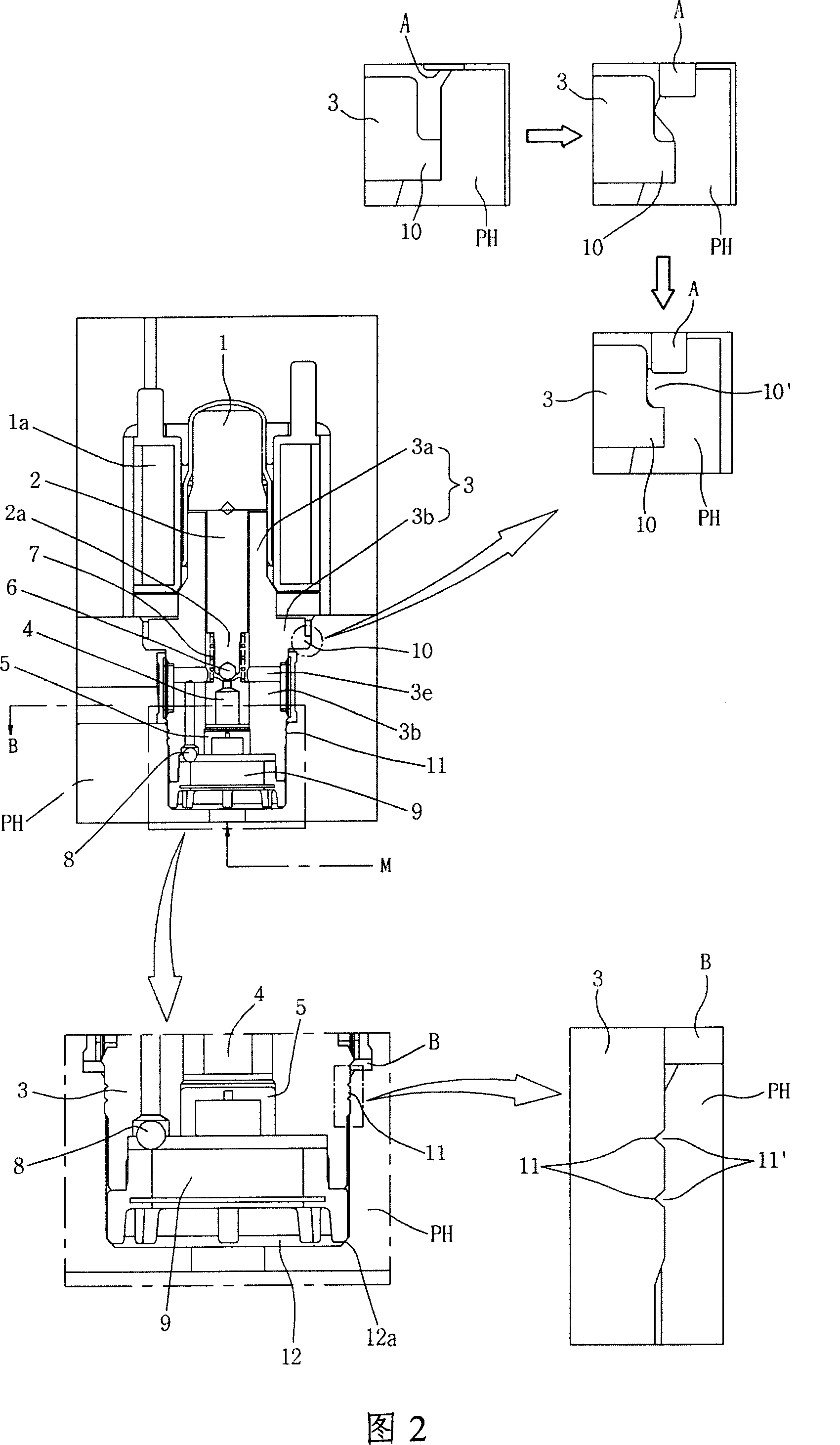
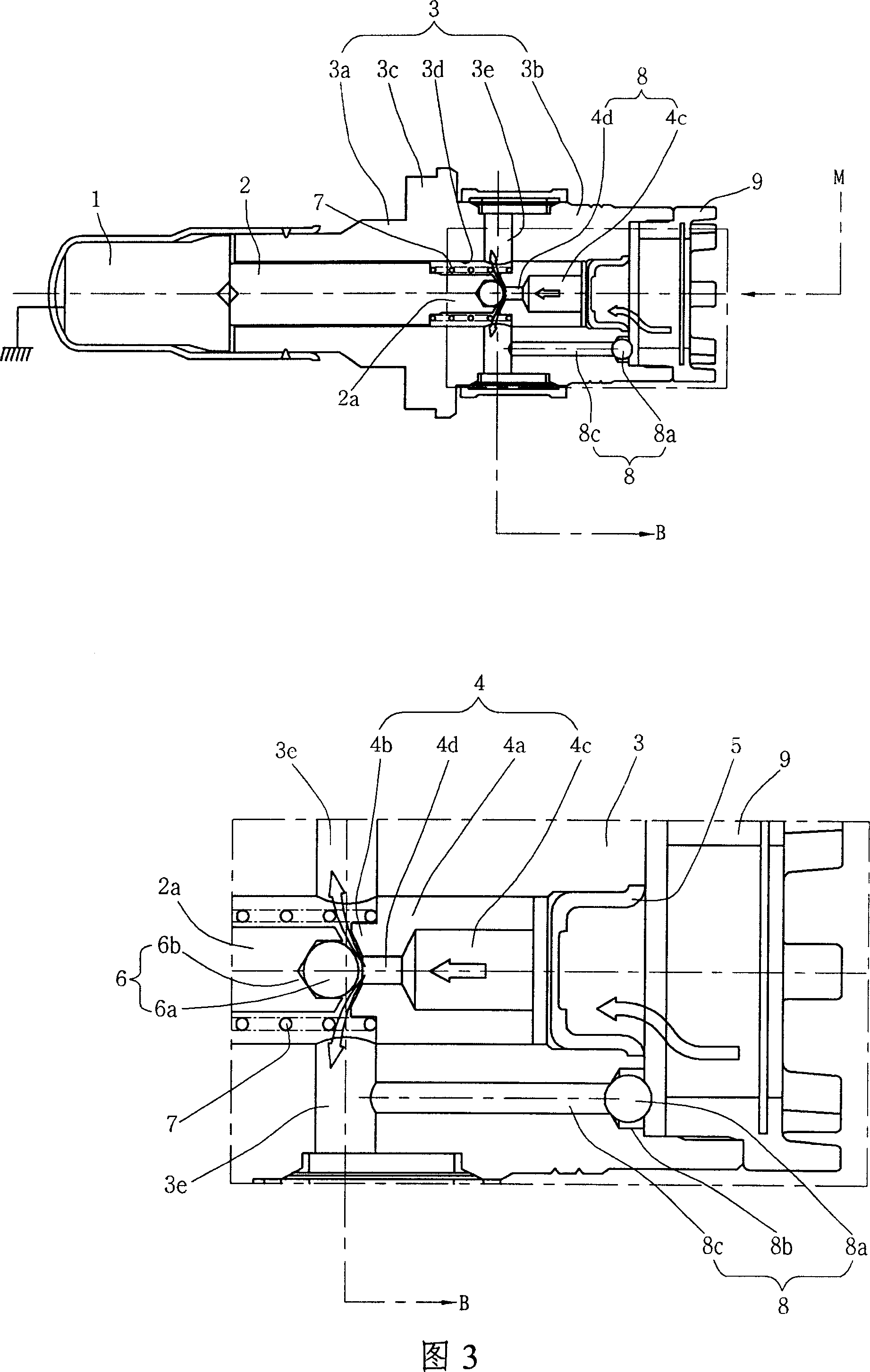
[0022] The invention is illustrated in detail in the accompanying drawings with reference to a preferred embodiment of the invention. The same reference numerals in the drawings and the description shall denote the same component.

[0023] FIG. 1 is a structural sectional view of a solenoid valve for controlling the flow of brake fluid according to an embodiment of the present invention. According to the present invention, the solenoid valve plays a role of providing hydraulic braking force, which is generated by the master cylinder M and transmitted to the braking mechanism B of the wheel through a booster used to increase the stepping force of the brake pedal P. The solenoid valve consists of a plunger 2 actuated by an armature 1 wound with a coil 1a that provides the power to depress the brake pedal in response to a control signal from the control unit, switching the contact ends of the flow path 2a is formed at the end of the plunger 2; a valve body 3, which is installed ...


PUM


Abstract

A solenoid valve includes a valve body defining a chamber that receives a plunger actuated by an armature, having flow path forming holes which are radially defined to serve as flow paths of a brake hydraulic line extending between a master cylinder and a brake mechanism, and fitted into a pump housing, a plunger seat accommodated in the valve body and applied with hydraulic pressure supplied from the master cylinder, a main check valve that opens and closes the flow paths through detachment and attachment between the contact end of the plunger and the plunger seat to switch flow of hydraulic pressure from the plunger seat through the valve body to the brake mechanism, and a return check valve to return oil in an axial direction, which is parallel to the plunger seat axially accommodated in the chamber and perpendicular to the flow path forming holes.

Description

technical field [0001] The present invention relates to solenoid valves for automobiles, and more particularly to solenoid valves for controlling the flow of brake fluid. Background technique [0002] It is well known that in braking systems hydraulic pressure, which increases the step force applied by the driver to the brake pedal, is used to stop a moving vehicle. Since this braking system has a simple mechanism for clamping the rotating wheel and stopping or slowing down the rotation of the wheel, optimal braking performance according to the traveling situation of the vehicle and road conditions cannot be realized. [0003] In order to overcome the limitations of the simple braking system and improve the stability of the vehicle, an anti-lock braking system (ABS) is used to avoid wheel locking by properly adjusting the braking force applied to the wheels, which depends on Based on the calculated wheel slip rate based on wheel speed; or adopt a traction control system (TC...

Claims


Application Information

Patent Timeline
Patent Type & Authority Applications(China)
IPC IPC(8): B60T17/04B60T8/1755F16K31/06
CPCB60T8/363B60T8/3675B60T8/00
Inventor 朴成俊
Owner HYUNDAI MOBIS CO LTD
Why Eureka
Try Eureka