Main duct construction method laid down tunnel structure article

A technology of tunnel structure and construction method, which is applied in the direction of tunnels, tunnel linings, mining equipment, etc., and can solve the problems of difficult insertion into subsequent main pipelines, cumbersome operations, excessive manpower and material costs, etc.

Inactive Publication Date: 2007-12-26
NTS ENC
View PDF1 Cites 5 Cited by
  • Summary
  • Abstract
  • Description
  • Claims
  • Application Information

AI Technical Summary

Problems solved by technology

[0009] Although the applicant's prior application has the above-mentioned advantages and characteristics, it is transported into the main pipeline setting space formed in the underground pilot tube, and the pilot tube The diameter of the successively connected subsequent main pipes that have been set in front of the initial main pipe is the same as that of the initial main pipe. There

Method used


Image

  • Main duct construction method laid down tunnel structure article
  • Main duct construction method laid down tunnel structure article
  • Main duct construction method laid down tunnel structure article

Examples


Embodiment 1

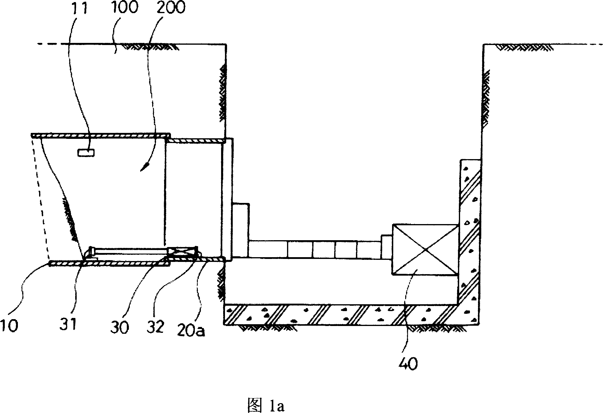
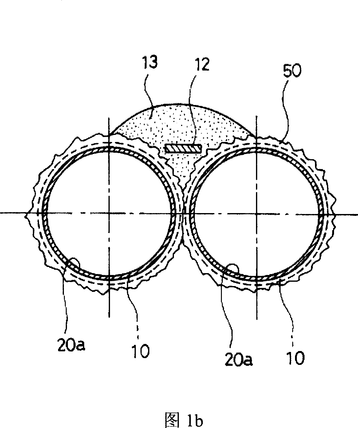
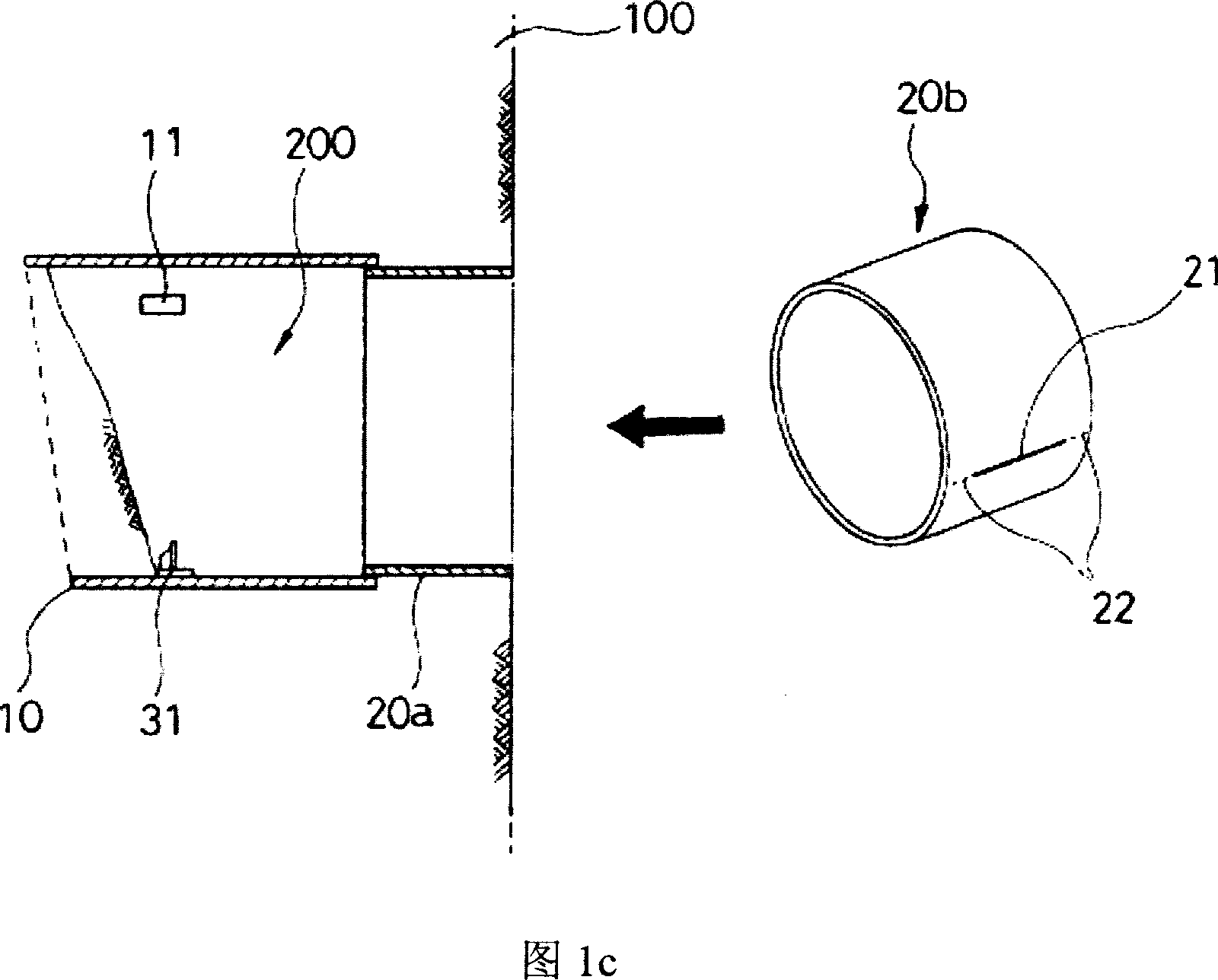
[0038]In order to lay tunnel structures in various forms suitable for terrain or underground conditions, the present invention connects and arranges circular main pipes made of steel pipes cut into predetermined lengths along straight lines or curves for long distances underground, including: as shown in Figure 1a, Before and after the inner surface of the pilot pipe 10 and the inside of the initial main pipe 20a inserted in the pilot pipe 10, a certain number of reaction platforms 31, 32 corresponding to each other are respectively arranged at predetermined intervals. Under the condition that the oil / pneumatic cylinder 30 load is respectively arranged between, utilize the oil hydraulic jack 40 to press the steps of the pilot pipe 10 and the initial main pipeline 20a in the underground 100; In the initial main pipeline 20a, excavate the surrounding soil through the input port 11 of the collapse prevention plate formed on the pilot pipe 10, and then, as shown in Figure 1b, put i...

Embodiment 2

[0046] In the present invention, as shown in Figure 2a, in order to lay tunnel structures in various forms suitable for terrain or underground 100 conditions, a circular main pipe 20 made of steel pipes cut to a predetermined length is arranged underground along a straight line or a curved line for a long distance. include:

[0047] Before and after the inner surface of the pilot pipe 10 and the inside of the inserted initial main pipe 20a, a certain number of reaction platforms 31, 32 corresponding to each other are respectively arranged at predetermined intervals, and between the reaction platforms 31, 32 on both sides of the advancing direction are respectively provided with Under the condition that the oil / pneumatic cylinder 30 is loaded, the steps of using the hydraulic jack 40 to press the pilot pipe 10 and the initial main pipe 20a underground 100;

[0048] When the pilot pipe 10 and the initial main pipe 20a are pressed in, the surrounding soil is dug out through the l...


PUM


Abstract

The invention discloses a main pipe construction method for establishing the tunnel formation, comprising following steps: pushing down a leading pipe and an initial main pipe underground; preventing landslide; conveying the next main pipe whose outer diameter is far smaller than the initial pipe to the inside of the main pipe setting space; expanding the diameter of the next main pipe to make it the same as the diameter of the initial main pipe; connecting the next main pipe after expansion treatment with the front end of the initial main pipe; repeating the connection operation of the next main pipe for establishing the tunnel formation. The technique scheme is able to construct in a direct or curve way, swift, safe and simple.

Description

technical field [0001] The present invention relates to the main pipeline construction method for laying tunnel structures that must be carried out in advance for laying straight or curved tunnels designed to adapt to terrain or underground conditions simply, quickly and firmly. Korean Patent Application No. 2004-91846 and Patent Application No. 2005-101768, which were previously applied by the applicant, can further significantly reduce the cost, and can complete the main pipeline construction more easily, quickly and safely. Background technique [0002] In general, in order to lay a tunnel, it is necessary to install a tunnel structure capable of withstanding the external stress of the tunnel. In the past, almost all tunnels were excavated to a certain depth in advance, and then erected using beams, iron plates, or corner timbers, etc., and then Set up the tunnel structure, repeat the above construction method in this way, and complete the tunnel laying. [0003] However...

Claims


Application Information

Patent Timeline
IPC IPC(8): E21D11/04
CPCE21D9/001E21D9/005E21D9/14E21D11/38
Inventor 金正允
Owner NTS ENC
Why Eureka
Try Eureka