Multielement positional phase shift keying modulation and demodulation method

A technology of phase-shift keying and demodulation method, which is applied in the direction of phase-modulated carrier system, etc., can solve the problems of inconvenient high-ary modulation, etc., and achieve the effects of flexible performance design and index adjustment, simple structure, and high spectrum utilization

Active Publication Date: 2007-12-26
苏州东奇信息科技股份有限公司
View PDF1 Cites 43 Cited by
  • Summary
  • Abstract
  • Description
  • Claims
  • Application Information

AI Technical Summary

Problems solved by technology

However, EBPSK generally only transmits binary symbols, which is not convenient for high-ary modulation

Method used


Image

  • Multielement positional phase shift keying modulation and demodulation method
  • Multielement positional phase shift keying modulation and demodulation method
  • Multielement positional phase shift keying modulation and demodulation method

Examples


Embodiment

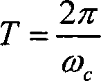
[0045] Embodiment: system parameter; Get carrier frequency f c = 465kHz, N = 10, phase deflection θ = 3 4 π , sample rate

[0046] f s =10f c = 4.65MHz, r g =0, then the carrier period T=1 / f c , symbol rate=1 / (10T)=46.5kHz.

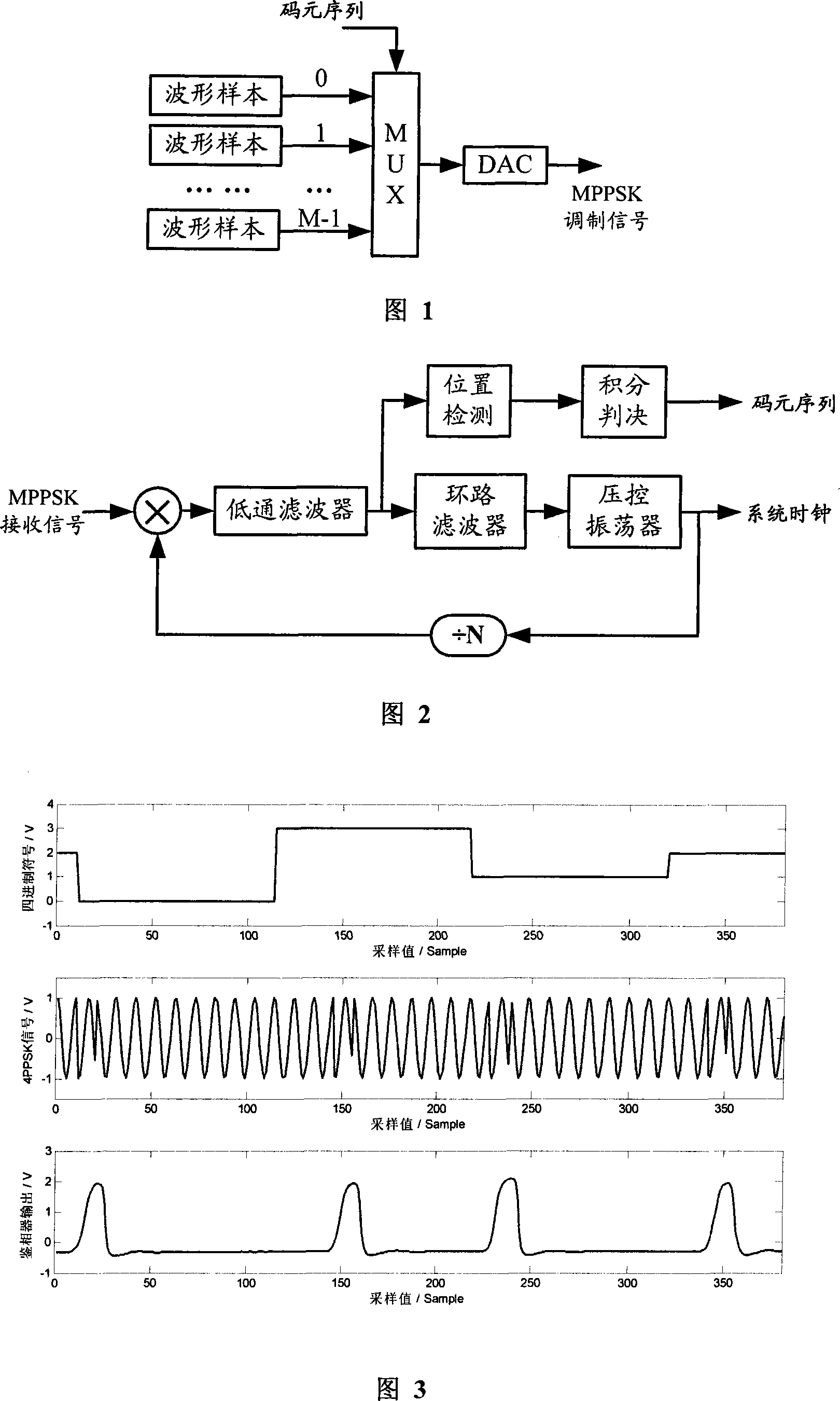
[0047] As shown in Figure 1, the sampling value of the basic waveform of the modulation symbol is stored in the waveform table, and the symbol value of the input symbol sequence is looked up in the table and the corresponding MPPSK modulated signal waveform is sent through the digital-to-analog converter (D / A). Using this hardware lookup table implementation, even if a non-zero guard interval r is inserted g , and will not add additional computation and overhead.

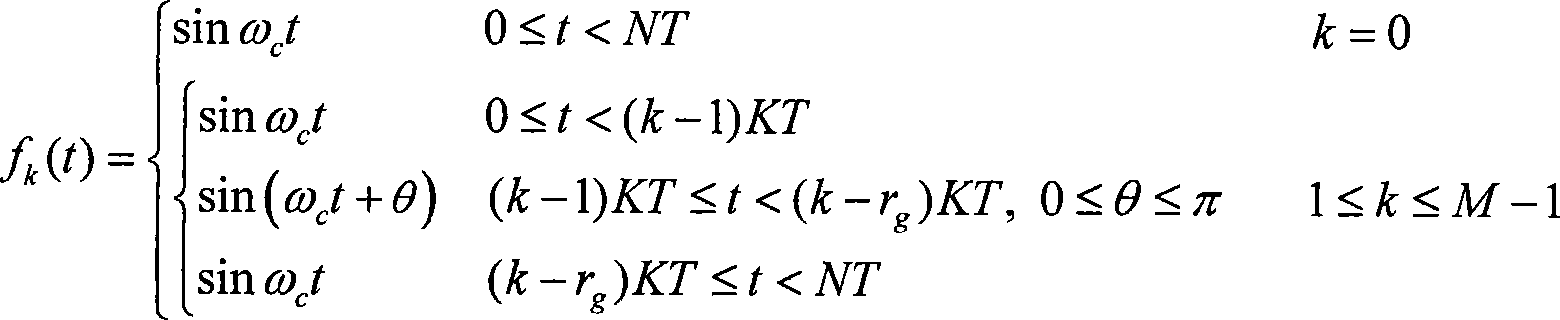
[0048] As shown in Figure 2, a signal demodulator structure based on a phase-locked loop is adopted. When carrier synchronization and symbol synchronization are realized, position detection and integral...


PUM


Abstract

The method comprises: using M-scale notation information symbols to directly control the location of sinusoidal carrier phase jump moment in each code element cycle, and inserting a certain guard gap to implement the modulation of M-element signals so as to realize the higher rate transmission in case of the symbol rate same with the EBPSK (extended binary phase shift keying) and same bandwidth occupation.

Description

technical field [0001] The invention relates to information modulation and demodulation in digital communication, in particular to a multi-position phase-shift keying modulation and demodulation method, which belongs to the technical field of high-efficiency digital information transmission. Background technique [0002] In a digital communication system, the process of moving binary data to a given transmission frequency band is called modulation, and the opposite process is called demodulation. In practice, we not only pursue the highest possible frequency band utilization, that is, transmit a higher digital rate (measured in bps / Hz) within the unit frequency band; we also hope to use the transmission energy more effectively to obtain better transmission effects . [0003] The applicant's previous patent application "unified binary phase modulation and demodulation method" (application number: 200610040767.2, publication number: CN1889550A), proposed a unified description...

Claims


Application Information

Patent Timeline
Patent Type & Authority Applications(China)
IPC IPC(8): H04L27/18
Inventor 吴乐南戚晨皓
Owner 苏州东奇信息科技股份有限公司
Why Eureka
Try Eureka